|
MARINE
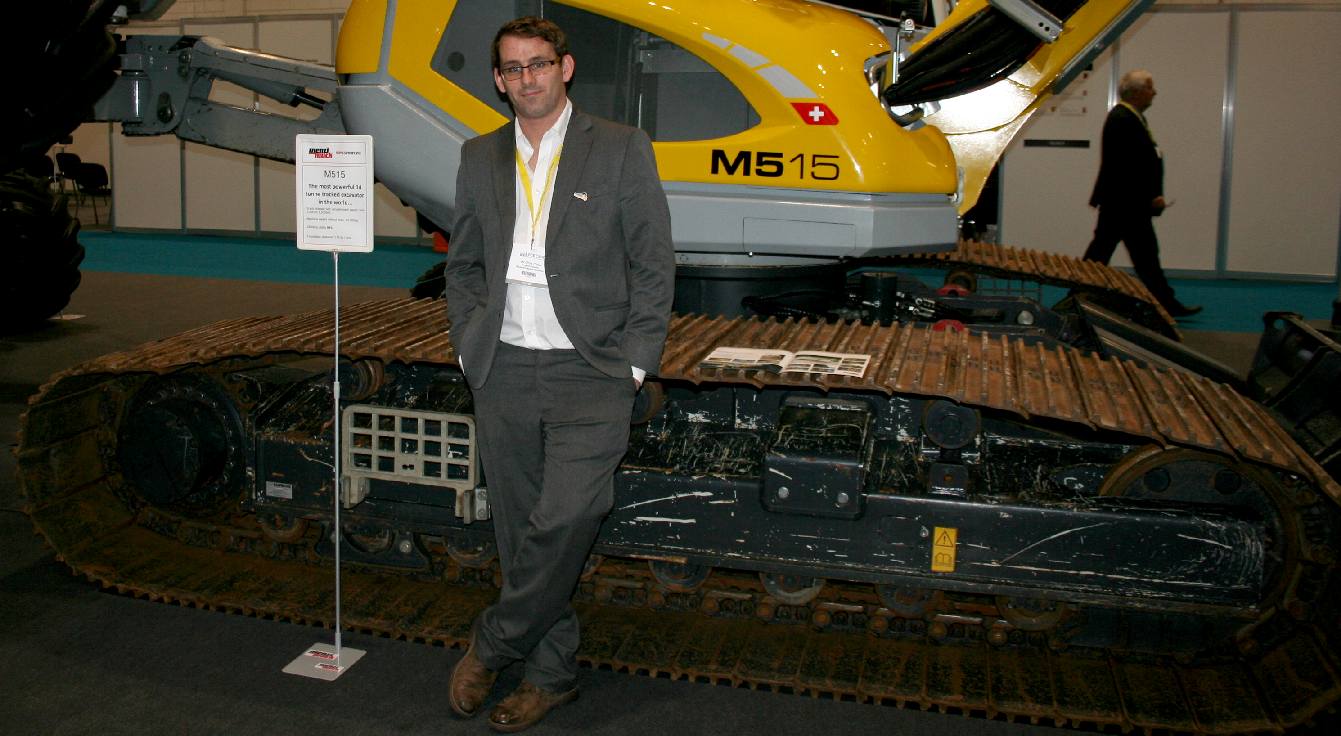
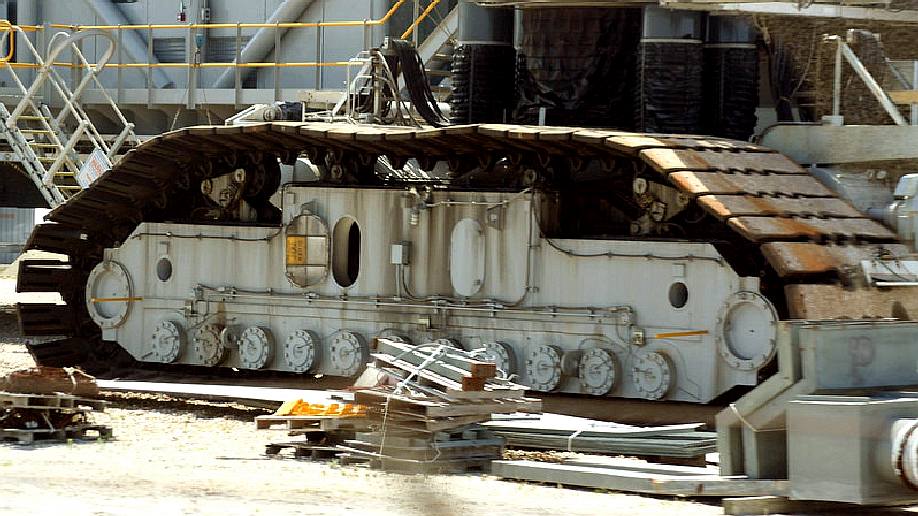
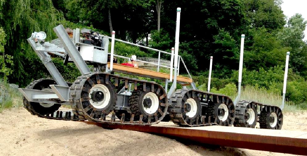
COASTAL ENGINEERING EXPO OCT 2016 EXCEL - Chris Close looks at other tracked
vehicles as to the possibility of using existing caterpillar tracked bogies for
the AmphiMax™ launch and recovery beach operations. These are steel tracks on
a frame without suspension. Copyright photograph 12 October 2016. You will need
the permission of Bluebird Marine Systems Ltd to be able to reproduce this
picture except for private study or educational purposes.
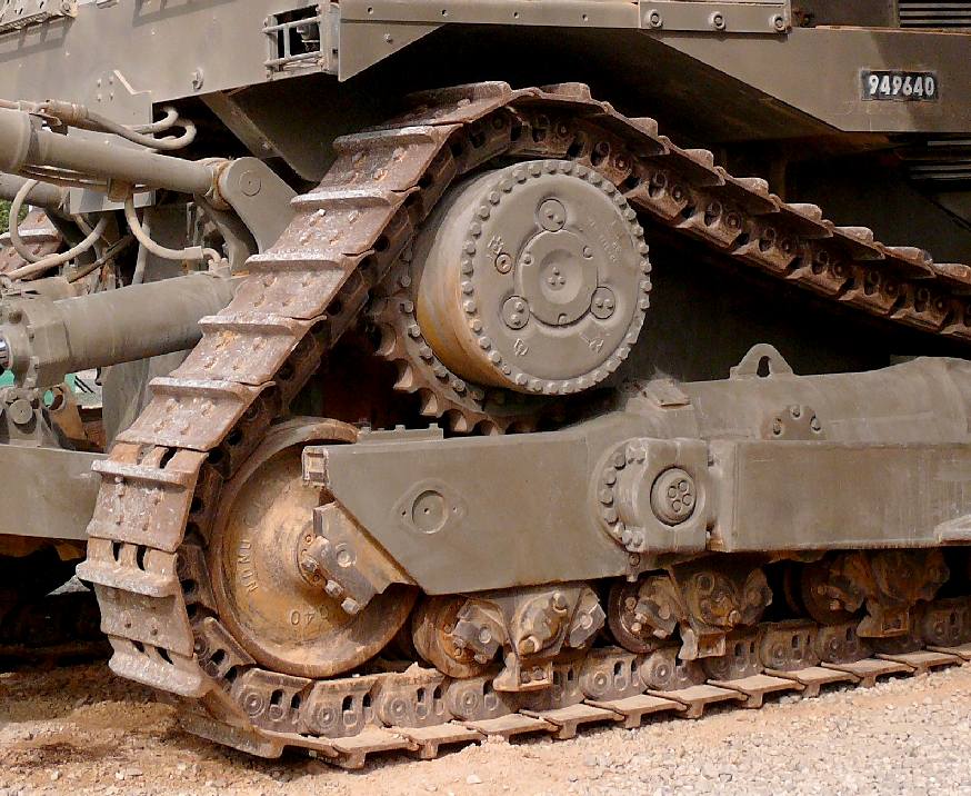
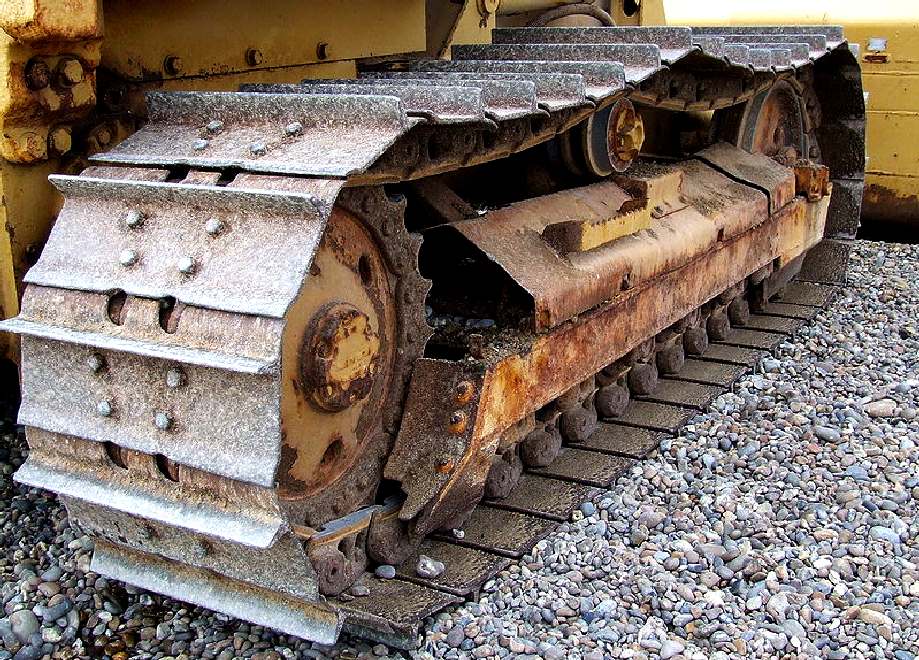
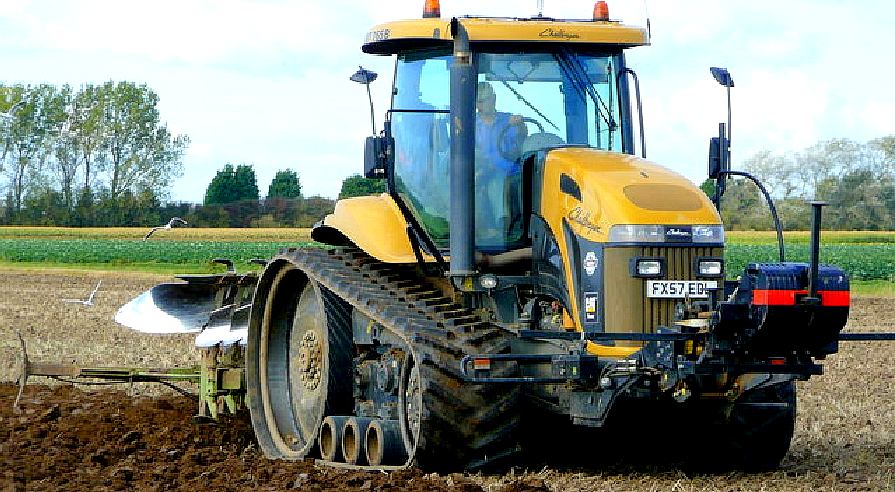
CATERPILLAR
TRACKS - A good example of an earth moving machine that uses steel links for
its tracks.
Continuous track, also called tank tread or caterpillar track, is a system of vehicle propulsion in which a continuous band of treads or track plates is driven by two or more wheels. This band is typically made of modular steel plates in the case of military vehicles and heavy equipment, or synthetic rubber reinforced with steel wires in the case of lighter agricultural or construction vehicles.
The large surface area of the tracks distributes the weight of the vehicle better than steel or rubber tyres on an equivalent vehicle, enabling a continuous tracked vehicle to traverse soft ground with less likelihood of becoming stuck due to sinking. The prominent treads of the metal plates are both hard-wearing and damage resistant, especially in comparison to
rubber tyres. The aggressive treads of the tracks provide good traction in soft surfaces but can damage paved surfaces, so some metal tracks can have rubber pads installed for use on paved surfaces.
Continuous tracks can be traced back as far as 1770 and today are commonly used on a variety of vehicles including bulldozers, excavators, tanks, and tractors, but can be found on any vehicle used in an application that can benefit from the added traction, low ground pressure and durability inherent in continuous track propulsion systems.
INVENTION
An effective continuous track was invented and implemented by Alvin Orlando Lombard for the Lombard Steam Log Hauler. He was granted a patent in 1901 and built the first steam-powered log hauler at the Waterville Iron Works in Waterville, Maine, the same year. In all, 83 Lombard steam
log haulers are known to have been built up to 1917, when production switched entirely to internal combustion engine powered machines, ending with a Fairbanks diesel-powered unit in 1934. Undoubtedly, Alvin Lombard was the first commercial manufacturer of the tractor crawler.
At least one of Lombard's steam-powered machines apparently remains in working order. A gasoline-powered Lombard hauler is on display at the Maine State Museum in Augusta. In addition, there may have been up to twice as many Phoenix Centipeed versions of the steam log hauler built under license from Lombard, with vertical instead of horizontal cylinders. In 1903, the founder of Holt Manufacturing, Benjamin Holt, paid Lombard $60,000 for the right to produce vehicles under his patent.
At about the same time a British agricultural company, Hornsby in Grantham, developed a continuous track which was patented in 1905. The design differed from modern tracks in that it flexed in only one direction, with the effect that the links locked together to form a solid rail on which the road wheels ran. Hornsby's tracked vehicles were given trials as artillery tractors by the British Army on several occasions between 1905 and 1910, but not adopted. The Hornsby tractors featured a track-steer clutch arrangement, which is the basis of the modern crawler operation. The
patent was purchased by Holt.
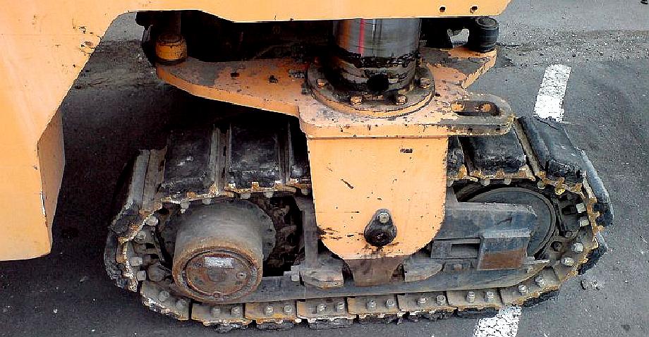
SUSPENSION
- These are the bearings that will allow the tracked bogies to accommodate
undulations in the sand - shingle in the case of the full size AmphiMax.
We are using pillow ball bearings with stainless steel bolts as the axle that
mounts to the underside of the wooden chassis. Copyright © February 1 2017 BMS
Limited all rights reserved. You will need the permission of Bluebird Marine
to copy these pictures except for educational use and associated research.
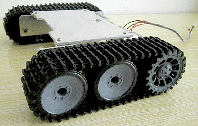
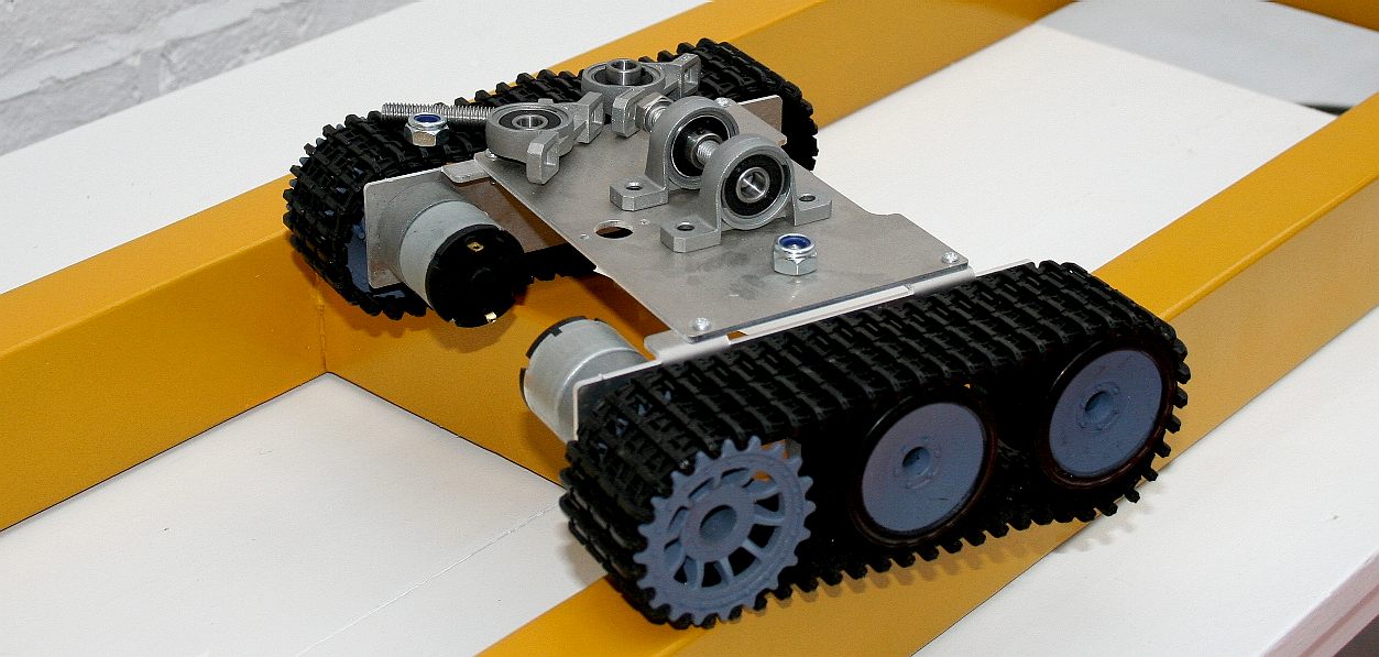
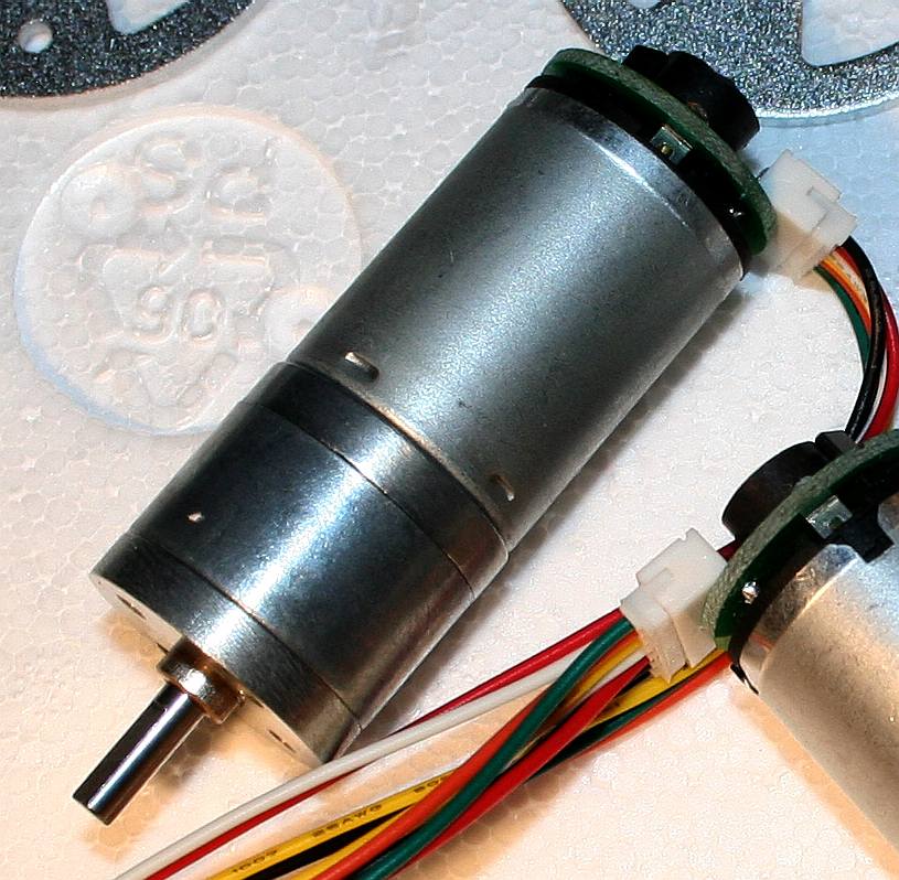
ROT-1
- A tracked vehicle chassis made of aluminium with reduction gearboxes and
a respectable torque load of 1.5kg 2kg @ 90 rpm. The dimensions of this
unit that is intended for robotics
use are: Length 18cm x Wide 24cm x High 6cm. the motor is 6 - 12 volts DC and
the cost via Alien Express is $55 US dollars per unit. Though you may have
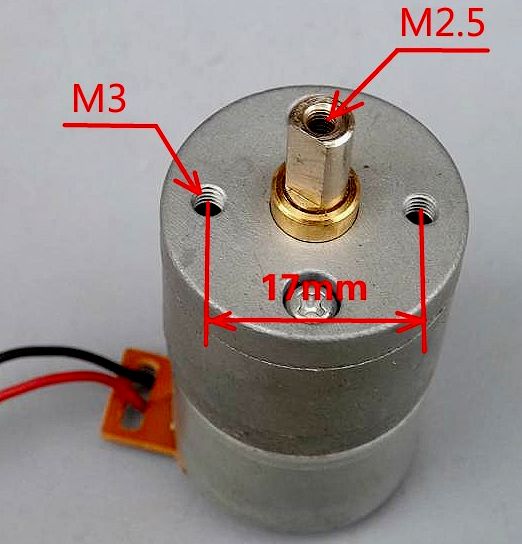
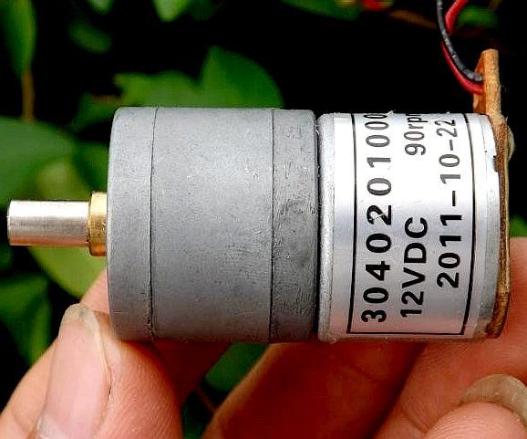
to pay import duty in some geographical locations. These are pictures of the 12v motor and
geartrain reduction unit for the ROT1 by Sinoning Robot, who do some nice Arduino
kit projects.
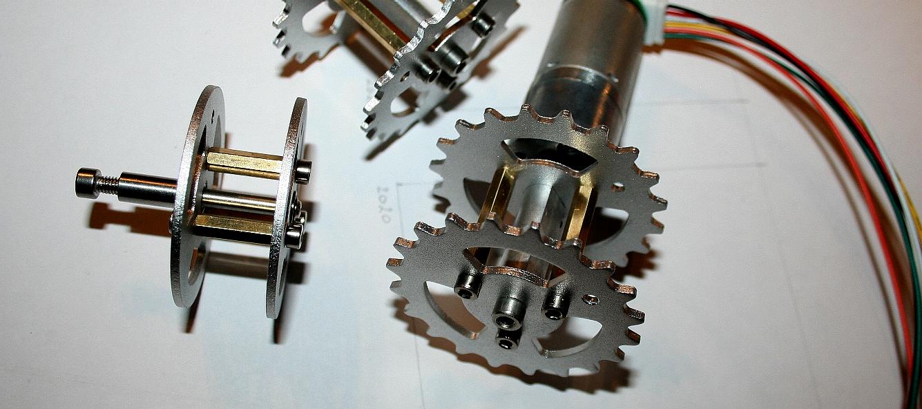
SPROCKETS
- The plastic items were fine for our initial tests, but we will be putting the
AmphiMax through some tough tests in the coming months so have made the decision
to upgrade to metal drive sprockets and idler wheels. Copyright © February 1
2017 BMS
Limited all rights reserved. You will need the permission of Bluebird Marine
to copy these pictures except for educational use and associated research.
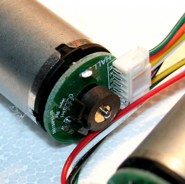
HALL
EFFECT
- These gearboxes have a much higher reduction ratio that those seen above
and on the end of the motors we have hall effect sensors that allow roboteers
greater control of their vehicles using the positional feedback. The snag with
this setup is that they are more difficult to waterproof than the units without
the electronics attached. We will think of something. Copyright © February 1
2017 BMS
Limited all rights reserved. You will need the permission of Bluebird Marine
to copy these pictures except for educational use and associated research.
THE
NAME CATERPILLAR
The name came from a soldier during the tests on the Hornsby crawler, '…trials began at Aldershot in July 1907. The soldiers immediately christened the 70bhp No.2 machine the "caterpillar"'.'
Holt adopted that name for his "crawler" tractors. Holt began moving from steam to gasoline-powered designs, and in 1908 brought out the 40 horsepower "Holt Model 40 Caterpillar". Holt incorporated the Holt Caterpillar Company, in early 1910, later that year trademarked the name "Caterpillar" for his continuous tracks.
In a memorandum of 1908, Antarctic explorer
Robert Falcon Scott presented his view that man-hauling to the South Pole was impossible and that motor traction was needed. Snow vehicles did not yet exist however, and so his engineer Reginald Skelton developed the idea of a caterpillar track for snow surfaces. These tracked motors were built by the Wolseley Tool and Motor Car Company in Birmingham, tested in Switzerland and Norway, and can be seen in action in Herbert Ponting's 1911 documentary film of Scott's Antarctic Terra Nova Expedition (at minute 50, here). Scott died during the expedition in 1912, but expedition member and biographer Apsley Cherry-Garrard credited Scott's "motors" with the inspiration for the British
World War I tanks, writing: Scott never knew their true possibilities; for they were the direct ancestors of the 'tanks' in
France.
During World War I Holt tractors were used by the British and Austro-Hungarian armies to tow heavy artillery and stimulated the development of tanks in several countries. The first tanks to go into action, the Mark I, built by
Great
Britain, were designed from scratch and were inspired by, but not directly based on the Holt. The slightly later French and
German tanks were built on modified Holt running gear.
Caterpillar Tractor Company began in 1925 from a merger of the Holt Manufacturing Company and the C. L. Best Tractor Company; an early successful manufacturer of crawler tractors.
With the Caterpillar D10 in 1977 Caterpillar resurrected a design by Holt and Best, the high-sprocket-drive, since known as the "High Drive", which had the advantage of keeping the main drive shaft away from ground shocks and dirt, and is still used in their larger dozers.
ADVANTAGES
Tracked vehicles have better mobility than pneumatic tyres over rough terrain. They smooth out the bumps, glide over small obstacles and are capable of crossing trenches or breaks in the terrain. Riding in a fast tracked vehicle feels like riding in a
boat over heavy swells. Tracks are tougher than tyres since they cannot be punctured or torn. Tracks are much less likely to get stuck in soft ground, mud, or snow since they distribute the weight of the vehicle over a larger contact area, decreasing its ground pressure. In addition, the larger contact area, coupled with the cleats, or grousers, on the track shoes, allows vastly superior traction that results in a much better ability to push or pull large loads where wheeled vehicles would dig in. Bulldozers, which are most often tracked, use this attribute to rescue other vehicles, (such as wheel loaders) which have become stuck in, or sunk into, the ground. Tracks can also give higher maneuverability, as tracked vehicles can turn in place without forward or backward movement by driving the tracks in opposite directions. In addition, should a track be broken, assuming the correct tools are available, it can be repaired without the need for special facilities;
a possible advantage in a combat situation.
The seventy-ton M1 Abrams tank has an average ground pressure of just over 15 psi (100 kPa). Since tyre air pressure is approximately equal to average ground pressure, a typical car will have an average ground pressure of 28 psi (190 kPa) to 33 psi (230
kPa).
DISADVANTAGES
The disadvantages of tracks are lower
top speed, much greater mechanical complexity, shorter life and the damage that their all-steel versions cause to what passes beneath them. They are assumed to severely damage hard terrain like asphalt pavement, but actually have significantly lower ground pressures than equivalent or lighter wheeled
vehicles. However, they often cause damage to less firm terrain such as lawns, gravel roads, and farm fields, as the sharp edges of the track easily rout the turf. Accordingly, vehicle laws and local ordinances often require rubberised tracks or track pads. A compromise between all-steel and all-rubber tracks exists: attaching rubber pads to individual track links ensures that continuous track vehicles can travel more smoothly, quickly, and quietly on paved surfaces. While these pads slightly reduce a vehicle's cross-country traction, in theory they prevent damage to any pavement.
WHEELS
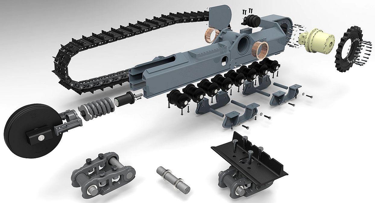
v TRACKS - A really useful exploded diagram of the parts for one side of a
quality dual-track undercarriage. Two tracks are needed for stability and
steerability.
Additionally, the loss of a single segment in a track immobilizes the entire vehicle, which can be a disadvantage in situations where high reliability is important. Tracks can also ride off their guide wheels, idlers or sprockets, which can cause them to jam in an overly tight position or to come completely off the guide system (this is called a 'thrown' track). Jammed tracks may become so tight that the track may need to be broken before a repair is possible, which requires either explosives or special tools. Multi-wheeled vehicles, for example, 8 X 8 military vehicles, may often continue driving even after the loss of one or more non-sequential wheels, depending on the base wheel pattern and drive train.
Many manufacturers provide rubber tracks instead of steel, especially for agricultural applications. Rather than a track made of linked steel plates, a reinforced rubber belt with chevron treads is used. In comparison to steel tracks, rubber tracks are lighter, make less noise, create less maximal ground pressure and do not damage paved roads. The disadvantage is that they are not as solid as
steel tracks. Previous belt-like systems, such as those used for half-tracks in World War II, were not as strong, and during military actions were easily damaged. The first rubber track was invented and constructed by Adolphe Kégresse and patented in 1913; rubber tracks are often called Kégresse tracks.
Prolonged use places enormous strain on the drive transmission and the mechanics of the tracks, which must be overhauled or replaced regularly. It is common to see tracked vehicles such as bulldozers or tanks transported long distances by a wheeled carrier such as a tank transporter or train, though technological advances have made this practice less common among tracked military vehicles than it once was.
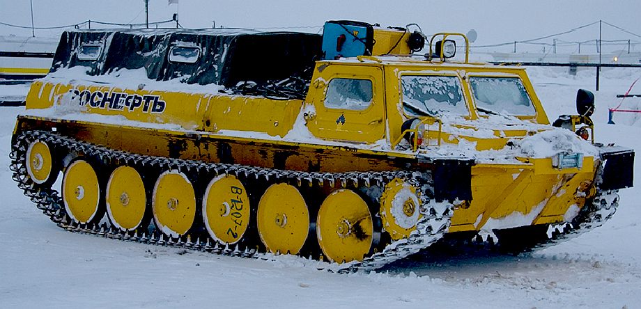
ICY
GROUND - A Russian tracked vehicle used to service oil production facilities
where grip is needed in harsh arctic conditions.
CONSTRUCTION
Modern tracks are built from modular chain links which together compose a closed chain. The links are jointed by a hinge, which allows the track to be flexible and wrap around a set of wheels to make an endless loop. The chain links are often broad, and can be made of manganese alloy steel for high strength, hardness, and abrasion resistance.
Track construction and assembly is dictated by the application. Military vehicles use a track shoe that is integral to the structure of the chain in order to reduce track weight. Reduced weight allows the vehicle to move faster and decreases overall vehicle weight to ease transportation. Since track weight is completely unsprung, reducing it improves suspension performance at speeds where the track's momentum is significant. In contrast, agricultural and construction vehicles opt for a track with shoes that attach to the chain with bolts and do not form part of the chain's structure. This allows track shoes to break without compromising the ability of the vehicle to move and decrease productivity but increases the overall weight of the track and vehicle.
The vehicle's weight is transferred to the bottom length of track by a number of road wheels, or sets of wheels called bogies. Road wheels are typically mounted on some form of suspension to cushion the ride over rough ground. Suspension design in military vehicles is a major area of development; the very early designs were often completely unsprung. Later-developed road wheel suspension offered only a few inches of travel using springs, whereas modern hydro-pneumatic systems allow several feet of travel and include shock absorbers. Torsion-bar suspension has become the most common type of military vehicle suspension. Construction vehicles have smaller road wheels that are designed primarily to prevent track derailment and they are normally contained in a single bogie that includes the idler-wheel and sometimes the sprocket.
Transfer of power to the track is accomplished by a drive wheel, or drive sprocket, driven by the motor and engaging with holes in the track links or with pegs on them to drive the track. In military vehicles, the drive wheel is typically mounted well above the contact area on the ground, allowing it to be fixed in position. In agricultural crawlers it is normally incorporated as part of the bogie. Placing suspension on the sprocket is possible, but is mechanically more complicated. A non-powered wheel, an idler, is placed at the opposite end of the track, primarily to tension the track, since loose track could be easily thrown (slipped) off the wheels. To prevent throwing, the inner surface of the track links usually have vertical guide horns engaging grooves, or gaps between the doubled road and idler/sprocket wheels. In military vehicles with a rear sprocket, the idler wheel is placed higher than the road wheels to allow it to climb over obstacles. Some track arrangements use return rollers to keep the top of the track running straight between the drive sprocket and idler. Others, called slack track, allow the track to droop and run along the tops of large road wheels. This was a feature of the Christie suspension, leading to occasional misidentification of other slack track-equipped vehicles.
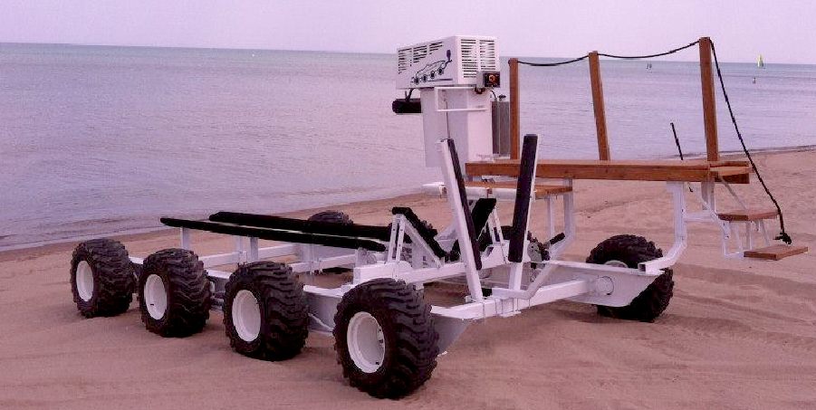
WHEELS
v TRACKS - The beach launcher above is seen here with rubber tyres on
steel wheels. It is an elegant solution to the age old problem of beach
launching and recovery using a trailer and towing vehicle. The trailer system
has the advantage of range - provided that the trailer system can cope with the
boat load - and this is where it all starts to fall apart. The traction of these
all terrain treads is fine for lighter launch and recovery operations, but for
heavier loads on some beaches tracks are seen as not so much an advantage, but
essential to the effectiveness of the concept.
TRACKS
v WHEELS - Okay, so add tracks to your wheels and you will increase the
surface area spread and increase traction, but the other advantage of tracks is
not realized, in that the circumference of the driven wheel is still the same,
whereas, with a sprocket and track system, the circumference of the driven wheel
is much less in proportion to the grip, so increasing available torque from the
hydraulic motors, or eliminating the need for so much reduction gearing if you
prefer.
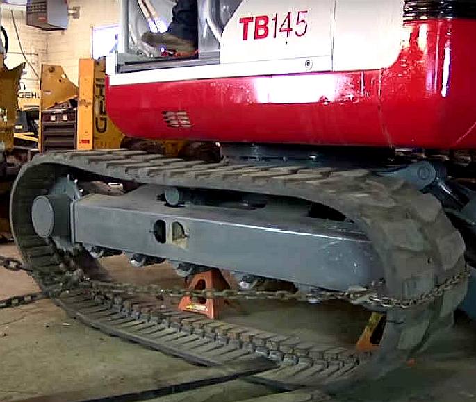
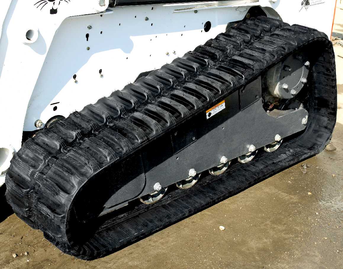
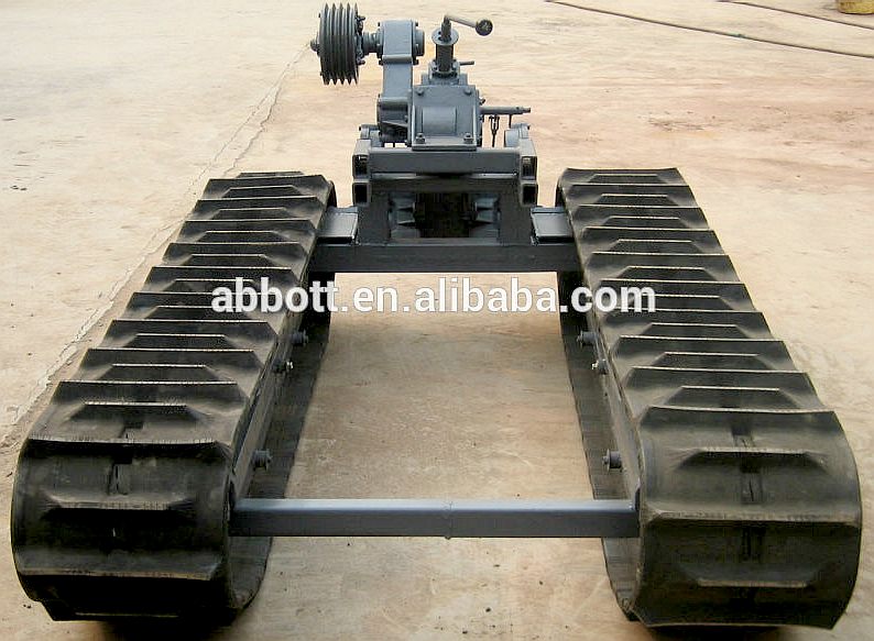
MINI
EXCAVATORS - These are rubber caterpillar tracks from the Takeuchi and
Bobcat series of small hydraulic diggers.
Youtube
LINKS
& REFERENCE
https://www.alibaba.com/product-detail/Rubber-track-drive-chassis-whole-crawler_60079759504.html
https://www.alibaba.com/product-detail/Steel-Track-Undercarriage_60003318241.html?s=p
http://www.crawlertracksystem.com
https://en.wikipedia.org/wiki/Continuous_track
 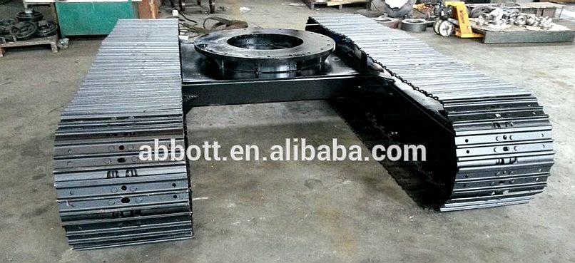
 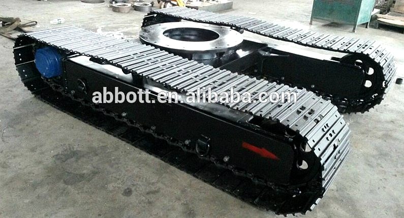
UNDERCARRIAGES -
A number of companies specialize in producing tracked undercarriages of various
weights and for different applications, such as those seen above on the famous
Alibaba website. Eight 12 ton capacity units are likely to weight 3,500kg each
for a total of 28,000kg or 61,712lbs (27 tons). The steel for the chassis and
cab are likely to be around 15 tons and the engines and hoses at least another 5
tons. Hence, the AmphiMax is sure to weigh at least 47 tons, leaving 45 tons
load carrying capacity to launch a SeaVax.
AMPHIBIOUS
LAUNCH - AMPHIMAX
- CAB
- CHASSIS
- CRANE
- DIESELS -
FLOATATION - GENERATORS
- HYDRAULICS
- LAUNCH
SITE - MODEL
1/20 - TIMETABLE -
TRACKS
- TRAILER
- THRUSTERS - WHEELS


|