|
The frame or chassis of the AmphiMax is
made up of 18 triangulated sub-assemblies. These sub-assemblies are fabricated
from RHS (Rolled Hollow Section) tubing and then assembled to make the complete
AmphiMax chassis. We will use a combination of welding and
bolt fixings to complete
the chassis to:
a)
simplify fabrication
b)
reduce cost
c)
speed up production, and
d)
allow disassembled storage
WHEELED
SOLUTION
|
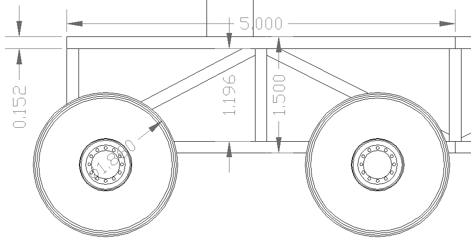
WHEELS
- SIDE
VIEW - This is a diagram of one of the chassis sub-assemblies that go
together to make the AmphiMax transporter main frame, here showing the
wheeled design. Eighteen of these
space-frames are welded and bolted together to make the completed vehicle
chassis. Earth moving floatation tyres are shown here with an 1860mm OAD.
These are more likely to be tractor tyres and rims for economy when this
part of the project costings are complete. Dimensions are in Meters.
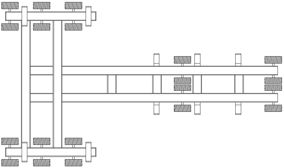
TEN
AXLES
- Shown here is a 10 axle (20 wheels) chassis. The idea of using one
design of axle potentially simplifies
production in that all the drive units are the same. It also means that twenty
smaller wheel-motors might be used - which may prove more economical.
Wheel-motors
use planetary reduction gearboxes to reduce the output rpm at an increase
in cost. An example is the Poclain MS125 (or
equivalent from the Bonfiglioli and Bosch/Rexroth) hydraulic motor ranges.
Couple these wheel-motors with the Poclain PL4H10 pumps or equivalent to
provide sufficient fluid flow to drive the wheels. See
the Eight-Axle
chassis with hydraulic circuit diagram. We
need to be able to source the best package for prospective SeaVax operators, where the
AmphiVax may be offered as an accessory for long-term fleet servicing, etc.
In New Zealand they use trailers like this (only smaller) to launch their
fishing fleets from a beach at Ngawi,
whereas at Hasting
in Sussex, they launch their fishing boats using wooden planks to slide
on. A trailer allows our Kiwi cousins to recover their boat and trailer
combos with a bulldozer, whereas in Sussex they are forced to use winches
to haul their boats out, because a bulldozer could not cope with the
friction of dragging a hull uphill along beach.

CROSS MEMBER
-
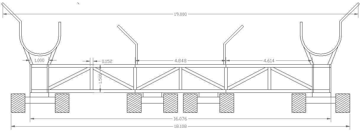
Six sub-assemblies go to make up the beam that joins the sponson support
members. Please note that
these drawings are Copyright © May 21 2016 Bluebird Marine Systems Ltd,
all rights reserved. You will need permission from the company to
reproduce these diagrams except for private study or review.
|
MOTIVATION
The final detailing of the chassis is subject to design of the axles. In turn
the axles depend on whether wheels (wheel-motors) or tracks, that are chosen. We will have to fabricate
our own mountings for axles of either system. This is likely to be from steel
tubing. We are not having (do not need) suspension as such, which helps to simplify this
stage of the manufacturing and assembly stages. Rubber
mounting may help to absorb shock loadings. If we have the time and money for
such a luxury, we will give it a shot.
In
the case of using wheels and tyres, we
have thought about mounting the wheel-motors directly to the chassis and will
keep this in mind. The problem here is ground clearance. Whatever scenario, we
will need to extend the underside of the main frame to provide mountings. In
these circumstances an axle may have the upper hand.
The
theoretical maximum speed of the vehicle is roughly the same for wheels or
caterpillar (type) tracks, though wheels would give an advantage on road due to
a lower rolling resistance, on a shingle beach we are looking for traction, when
tracks offer a significant advantage due to increased contact area. The problem
is then one of cost benefits. With large diameter tyres, we'd need Poclain MS125
wheel-motors, or equivalent to achieve 50 RPM (max), and so stay within the
capabilities of a hydraulic system. With a caterpillar tracked system we can
stay within the 140 RPM operating range of the MS35 hydraulic motor.
TRACKED
SOLUTION
|
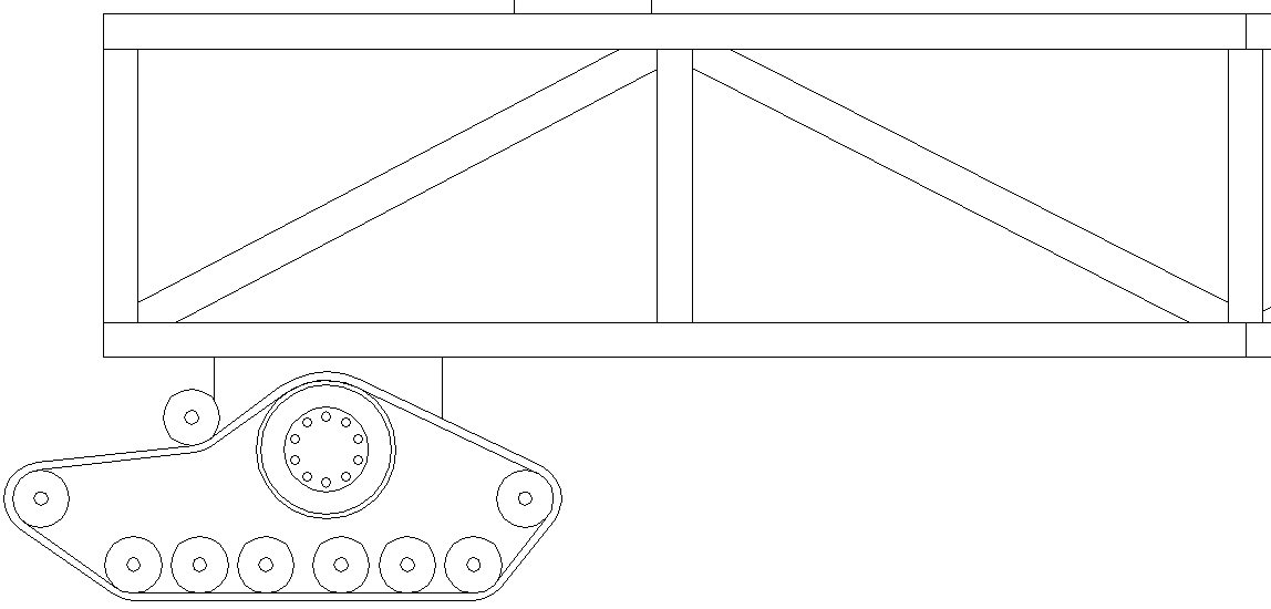
TRACKED
BOGIE - SIDE
VIEW - This is a diagram of the same chassis sub-assembly, but
with a tracked bogey instead of a wheel. These tracks are 30" wide
(762mm), 96" (2440mm) long and 39.25" high (1000mm), but the
surface area in contact with the beach is significantly improved. We have
yet to cost this arrangement or find a supplier.
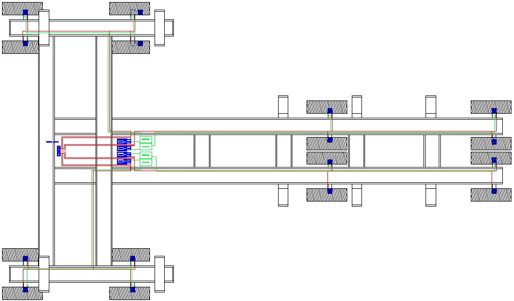
HYDRAULICS
- This is what the chassis looks like in plan view using tracked bogies.
The hydraulic circuit and general layout is the same. Turning will mean
stopping the port or starboard tracks, or even reversing the tracks on the
inside turning radius.

CHASSIS
SIDE VIEW - Here we see the chassis frame fitted with track bogies.
Tracks offer another engineering advantage over wheels, in that the
rotation of the driving cog requires much less torque from the smaller
diameter - in this case a shade over 24" (610mm) for the driven cog.
An MS35 hydraulic motor with suitable planetary reduction could power a
bogie for a land speed of 7.737mph per hundred rpm, for a max speed of
10.83mph at their 140rpm maximum rating.
TRACKED
CROSS MEMBER
- Once again, we see the cross-member of the space-frame, but with tracked
bogies. Please note that
these drawings are Copyright © June 2 2016 Bluebird Marine Systems Ltd,
all rights reserved. You will need permission from the company to
reproduce these diagrams except for private study or review.
|
LINKS
& REFERENCE
.
AMPHIBIOUS
LAUNCH - AMPHIMAX
- CAB
- CHASSIS
- DIESELS -
FLOATATION - HYDRAULICS
- LAUNCH
SITE - MODEL
1/20 - TIMETABLE -
TRACKS
- TRAILER
- THRUSTERS - WHEELS


|


