|
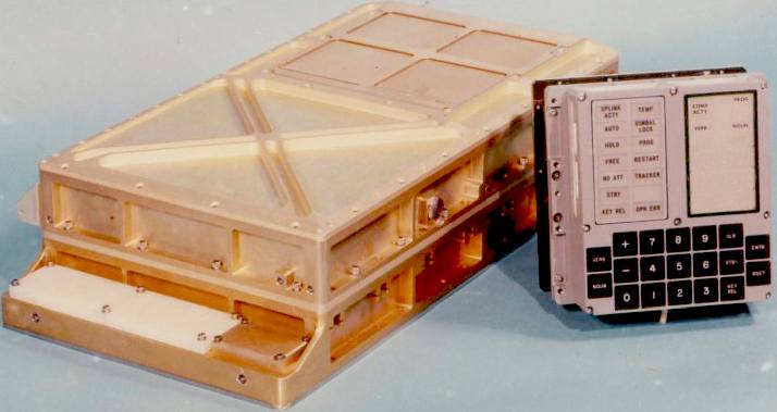
SEAVAX™ - PLASTIC SHREDDING & GRADING SCOOP
|
||||||||||||||||||||||||||||||||||||||||||||||||||||||||||||
|
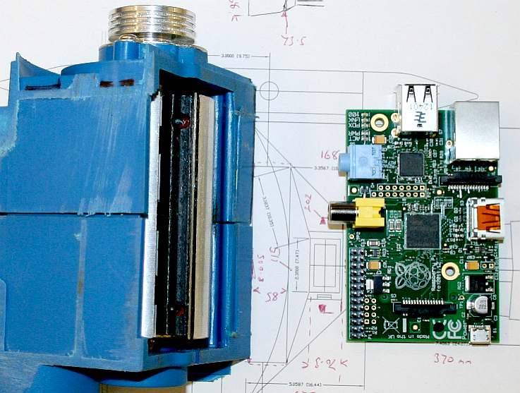
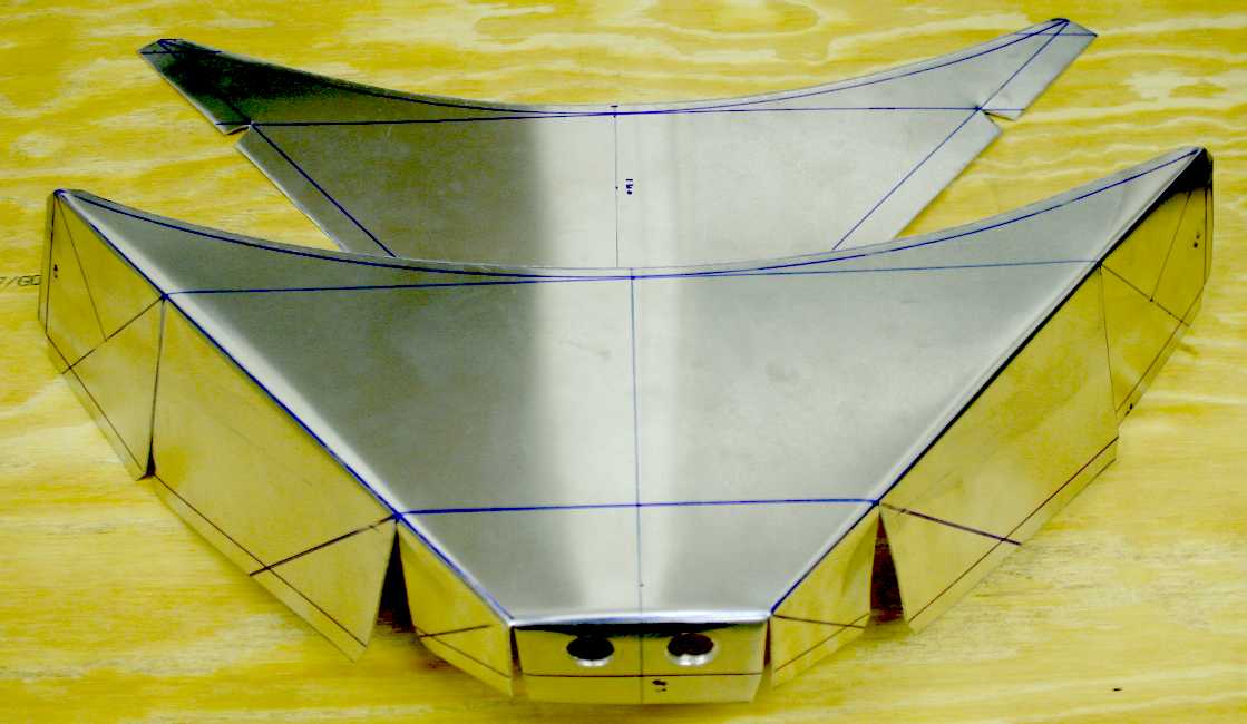
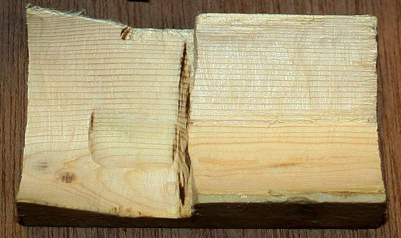
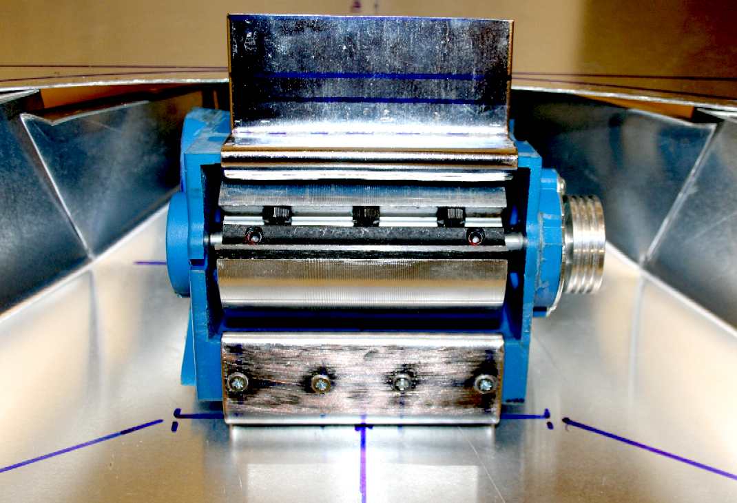
PLASTICS MILL - The SeaVax project is an opportunity to open up robotics to new fronts. Our treatment system involves identifying plastic in seawater, such as to be able to engage the appropriate onboard machinery, hence operate these giant ocean dustcarts efficiently. The picture above is of one of our first test, 'shredding heads.'
There are several stages of treatment that need to be monitored and coordinated electronically. Computers offer an effective and flexible method of matching ship speed to a particular patch of plastic soup, while keeping the filtration and grading machinery operating at optimum levels. The processing power needed for these operations could easily be handled by an Arduino or Raspberry Pi micro-computer, though for the production ships, we may decide on other platforms.
GET INVOLVED - We'd welcome ideas and practical experimental input from hobbyists, schools and colleges. If you would like to get involved please email the SeaVax project manager, Chris, using our contacts page.
In 2016 this was design 'uncharted' territory and the subject of much experimentation. The object of this exercise was to perfect a machine that can intelligently operate to suck up plastic, at the same time avoiding marine biota. To be able to do this any vacuum head must be equipped with a range of sensors to feed information of the local environment (the sea) to the computers that control the machinery that treats the ocean plastic waste.
In 2016 an experiment in our test tank proved that plastic could be extracted from water littered with plastic granules and chunks. The shredder seen here only served to grade the larger chunks of plastic. It was not efficient and would not suffice for ocean cleaning duties where bottles and other solid plastic would be removed from the sea prior to micro filtration, that is the real challenge once a fleet of ocean dustcarts is removing incoming, rather than accumulated micro-plastics in our gyres. A system would have to be developed from the starting point (shredder) shown on this page. See the infographic below as to the challenge.
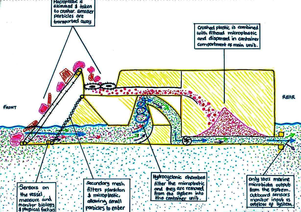
The chart below gives you an indication of the size of the biota and the filtration stages that SeaVax would use to separate large plastic objects from micro plastic particles, as compared to the marine life that we are seeking to protect.
The most difficult stage in terms of seawater filtration is where phytoplankton and zooplankton is mixed with micro plastic particles, commonly called a 'plastic soup.' By far the simplest stage filter wise is Stage 1, where a mesh is all that is needed to transport bulky plastic items into a hopper for granulation.
STAGE 1 - The Stage one mesh is small enough to prevent anything larger than a herring passing through and includes means of preventing fish from skipping onto the escalator, so ending up as sushi in the shredder.
STAGE 2 - Stage two is a variable opening low drag mesh that may be opened and closed in mouth size in relation to whatever water/life combination the SeaVax is sailing through. Zooplankton and phytoplankton may pass through this mesh, but not biota the size of krill, shrimps, anchovies or sardines.
STAGE 3 - Stage three is the most complex of the seawater filtration processes, involving computers and robotics allied to electronic sensors, to constantly tune hydro cyclonic and other devices to the medium that SeaVax is operating in. Pre and post chamber sensors read the seawater intake and exhaust to confirm that the operation is removing the micro plastic and not the biota, that would be returned to the ocean in good health.
Where a SeaVax may encounter a situation that it cannot tune itself to operate effectively, the craft may enter a standby mode, until conditions return to a more normal state.
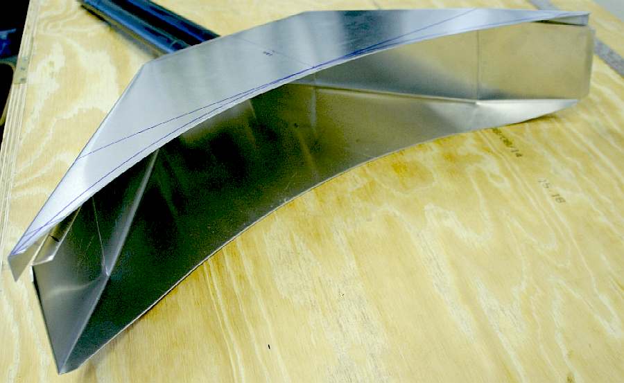
The head seen below is also, just the starting point for future experiments where the shape and area of the existing funnel could be vastly improved so that SeaVax vehicles would be more efficient.
HEAD SHAPE - The swept area is important as well as the depth of operation. If the swept area is increased by a factor of two, then the potential for collection is doubled with each sweep of the ocean, though sweep in terms of moving through the water is somewhat confusing if you include currents. We are working to increase collector head area of the SeaVax.
VARIABLE SELECTION - We are also working to define the ratio of final stage filtration to take into account the increase in energy needed as the particles become smaller. The area of theoretical area of any mesh increases if we are to keep our pumps running efficiently. The challenge is to be able to select the right area and mesh for the medium that SeaVax is operating in. The design of a self-cleaning variable mesh system in one of the next stages of evolution for SeaVax.
DIVERSION - The next challenge is to be able to siphon off (or divert) plastic from the flow taking advantage of the physical characteristics of the medium, while any marine life still present bypasses collection and returns to the sea unharmed. Before this stage, all efforts are to be made to avoid plastic soups with high concentrations of plankton - and to use other means to scare marine fauna away from the machinery.
Water filtration on an oceanic scale is thus not just limited to filtering water. The filtration strategy and deployment is just as important and the design of the machinery.
ROBOTIC VACUUM TECHNOLOGY
Robot machines are becoming more popular for domestic carpet cleaning and lawn mowing. Electrolux were one of the first into the market, with Dyson having joined in the fray in 2014 with their 360 Eye model. Some robots can even make the tea.
Where robot carpet cleaners plug into a mains supply for charging, a mobile, zero carbon cruiser needs to be fully autonomous if we do not want to create more pollution in any clean up process by using diesel or LNG. Using fossil fuels would also significantly reduce operating range from the need to constantly refuel. In any event, using diesel fuel would make any clean up effort way too expensive.
CONVENTIONAL SHREDDING MACHINES - A GOOD PLACE TO START
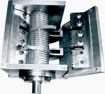
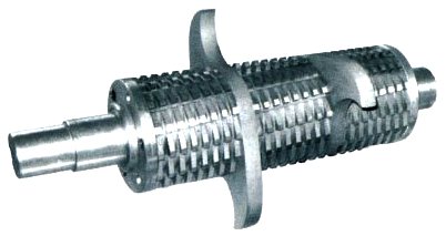
High-torque, slow-speed shredders combine ripping, breaking and shearing to grind larger chunks of flotsam that might be encountered. Industrial shredding mills are available that are designed to reduce the size of mixed bulky waste. The rotating heads need not turn more that 10-100 rpm and still cope with between 5-10 tons of plastic a day. You may see this as overkill, but in times of glut - such as in the middle of a rich plastic soup (north pacific gyre), it will speed up ocean cleaning if a SeaVax unit has a high capacity - and can deal with serious choking solids. High-torque, slow-speed shredder systems on land can process between 10-80 tons per hour with up to 80% volume reduction. We are only looking to be able to process up to 10 tons per nautical mile in the most extremely polluted ocean regions. This will constitute a windfall find, that will test any transfer system, where a SeaVax needs to be operating as much of the time as possible, and not sitting in the sea waiting to be emptied. Thus a train of low cost transport barges, or ships, is just as important as the effectiveness of the mobile powerhouses that do the collecting.
MULTI-STAGE HARVESTING HEAD
There will need to be several stages and methods of collecting the different types of waste. There is surface floating waste, such as from rivers - bottles, packaging and bags, and from ships - fishing nets and other larger industrial plastic products that will also need to be scooped from the ocean safely, then shredded.
Then there are the smaller particles that make up roughly 80% of the plastic in the 5, or is that really 7 gyres, including the one forming in the Arctic Ocean. We treat the North Pacific as two separate operational gyres. Other classification societies class the west and east swirling masses as one.
The smaller (macro) plastic bits float below the surface and various depths down to 3 meters. Shredding is not necessary, but we do not want to scoop up plankton or other small life-forms - just the plastic. The majority of plastic fragments are less than 1 cm in size – no bigger than your little fingernail – with a mass less than 0.15 g. This size particle will require a dedicated hydro-cyclonic chamber, or chambers. We don't want larger shredded waste passing through the hydro-cyclonic chambers. Smaller particles will need additional treatment. A similar technique is employed in the modern "dual-cyclone" vacuum cleaners made famous by Sir James Dyson. But vacuum cleaners do not have to shred solid articles such as bottles, nor can they.
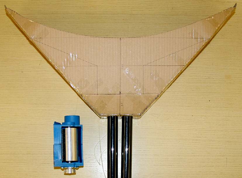
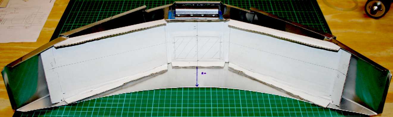
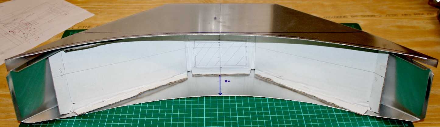
EXPERIMENTAL HEAD NUMBER ONE - Uncannily, the development for our 'base-line' collector head looks for all the world like the wings of one of the Ancient Egyptian sky gods: Nut. Even more of a coincidence is the fact that we have a sycamore tree in the grounds, where Nut is sometimes depicted by this tree.
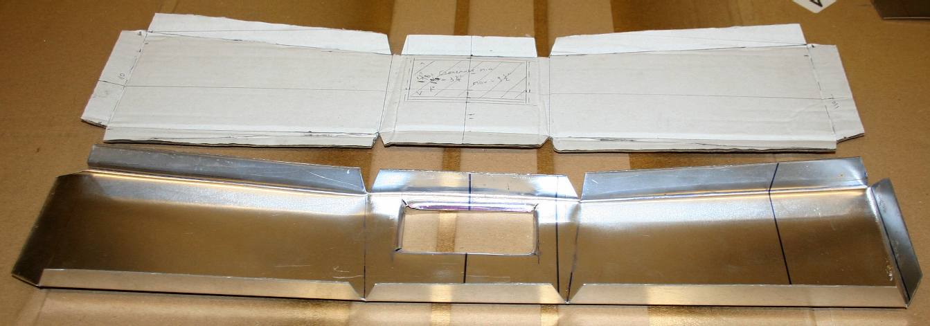
To keep costs down and speed up this research, work experience crew, under the direction of our project director, Chris Close, were given the task of mocking up the drawings in 1:20th scale, in cardboard from the master AutoCad files. What could take hours working in metal, can be proven in minutes with a sharp craft knife and some Sellotape. Does anyone out there remember Blue Peter? Here's one we prepared earlier.
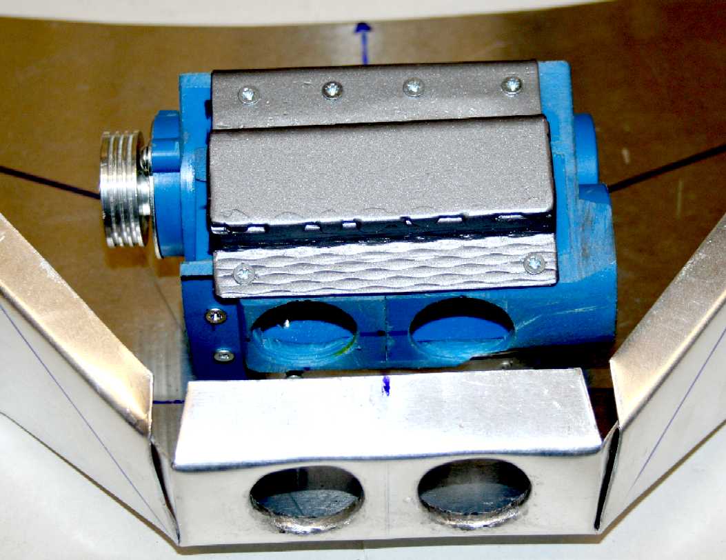
EXPERIMENTAL SHREDDER STAGE ONE - Looking a lot less Egyptian, the two cardboard developments are folded and taped together. The first of many test shredding heads (blue and alloy drum unit with tungsten blades on the lower left) fits neatly inside this underwater collector. The two tubes seen here suck in the water and any plastic particle soup that is collected by this head, then directs the mix into various treatment chambers for separation. The treatment sequence is at the moment proprietary information, so too the test results, once they are in. That is the reason we cannot go the whole hog. The shredding drum needs a motor to drive the blades at a speed, and with a force to be able to deal with tough plastic objects. We also need a safety cut out and clutching mechanism for when objects are encountered that may be harder than plastic. You'll love the off-the-shelf solution for this scale. See below.
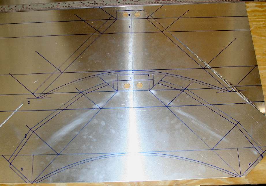
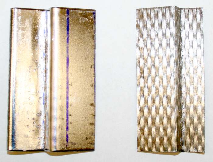
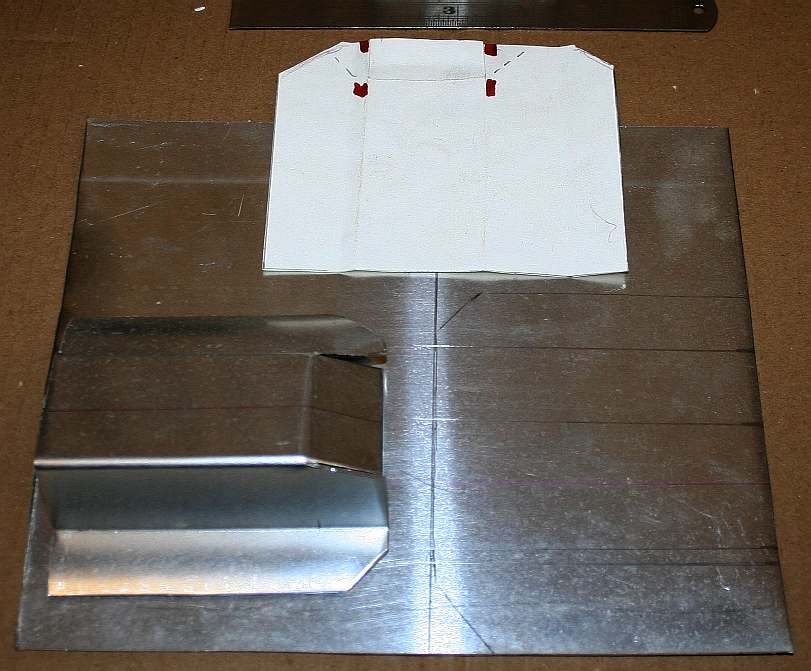
ALUMINIUM PRODUCTION - Spare a though for all the mining engineers, the smelters, foundries and rolling mills that convert the chief ore - bauxite - into this fabulously versatile material. With all the effort of digging it up and processing it, mark it out carefully so as not to waste material. The measurements above make good use of the sheet material, while also leaving a margin for safe cutting.
Aluminium (or
aluminum US) is a chemical element in the boron group with symbol Al and atomic number 13. It is a silvery-white, soft,
non-magnetic, ductile metal. Aluminium is the third most abundant element (after oxygen and silicon), and the most abundant metal in the Earth's crust. It makes up about 8% by weight of the Earth's solid surface. Aluminium metal is so chemically reactive that native specimens are rare and limited to extreme reducing environments. Instead, it is found combined in over 270 different minerals.
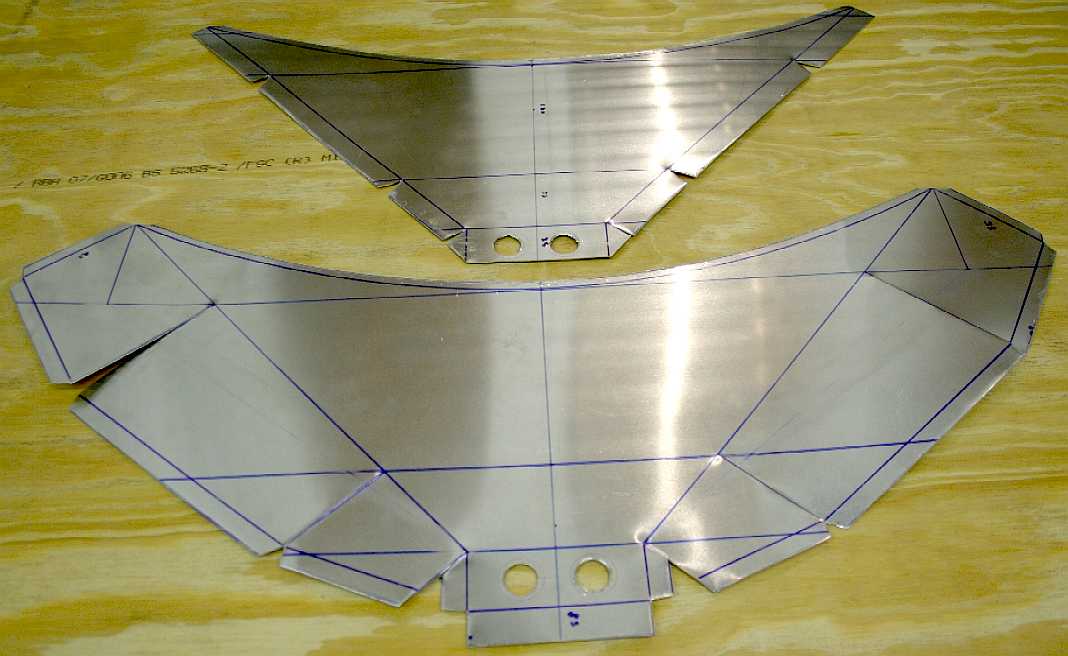
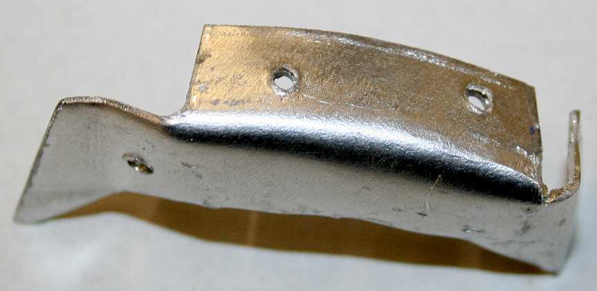
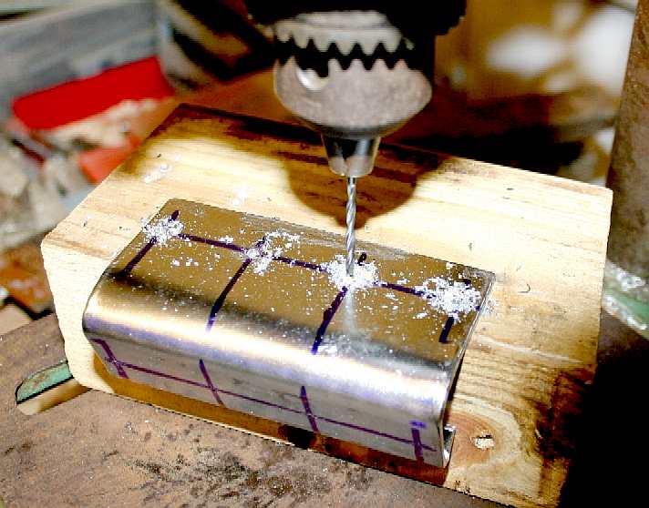
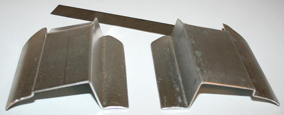
ALLOY SHEET - Now tested in cardboard, the developed dimensions are marked onto a sheet of aluminium alloy using a blue Staedtler Lumocolor permanent marker pen with a 1mm medium tip. We prefer 0.4mm pens, but they don't last long in a workshop environment. The 1mm tipped pens seem to go on and on. This particular blue pen was used to make a car body parts in 1997/8 - and the ink is still good. Most brands of pen would have dried up long ago. Note that there are two overlapping end plates with 20mm holes pre-drilled.
METAL FORMING - When designing for production, leave plenty of metal to make return folds, for welding, or riveting. The holes drilled in the end mounting plates are smaller in diameter than the suction tubing to allow for a lip to be formed that will spread, rather then concentrate loads. This is a double thickness plate where the lip on the inner plate faces into the chamber - and the lip on the outer faces into the seawater. This arrangement, though time consuming in needing panel beating, will make the suction tube bond that much stronger. The suction tubes take most of the loads going aft to the main hull, to a heavy duty hinge. At the front end of the suction head, there will be a height adjustment mechanism, also sharing some of the loads of handling what will be the world's largest vacuum cleaning head or scoop. Joseph Bamford, the founder of JCB, would have been proud. JCB is a UK manufacturer of articulated earth moving equipment, in competition with Caterpillar who make mining and construction plant in the US.
JAWS - The two alloy blanks are further formed so that one sits on top of the other. We would not want to be plastic floating in the ocean with this huge mouth bearing down on us. Fish and other fauna are rather more safe. Just like Bruce the shark in Finding Nemo, this robotic fisherman, will take an electronic oath not to treat fish as food, but as friends. This giant head, will be equipped with sensors to differentiate micro plastic from plankton. The bigger floating plastic is more easy to spot, as are larger fish and mammals, such as to avoid swallowing them. Split beam sonar is capable of identifying small particles. Other sensors will tell SeaVax robots the alkalinity, salinity, temperature and provide information of other elements present in a gyre.
MANTA RAY - You can see from the shape of the collector head and throat size in proportion to body width and length, why the prototype SeaVax is to be christened the Manta Ray. Once a perfect fit-up is achieved, the two folded sections will be joined - in this case with low-profile pop rivets. An internal divider will double as the mounting for the shredding head, that is a variable speed unit.
NUT (SKY GOD) - In Ancient Egyptian history, Nut is a daughter of Shu and Tefnut. She has five children: Osiris, Set, Isis, Nephthys and Horus. Her name is translated to mean 'sky' and she is considered one of the oldest deities among the Egyptian pantheon, with her origin being found on the creation story of Heliopolis. She was originally the goddess of the nighttime sky, but eventually became referred to as simply the sky goddess. Her headdress was the hieroglyphic of part of her name, a pot, which may also symbolize the uterus. Mostly depicted in nude human form, Nut was also sometimes depicted in the form of a cow whose great body formed the sky and heavens, a sycamore tree, or as a giant sow, suckling many piglets (representing the stars).
The Ancient Egyptians believed that a solar boat carried the sun around the back of the earth at sunset, bringing it back in the morning for sunrise.
HORUS - Horus served many functions in the Egyptian pantheon, most notably being a god of the sun, war and protection. You might possibly see the visual connection we made when making the suction head for SeaVax proof of concept model.
OSIRUS - Osiris was considered not only a merciful judge of the dead in the afterlife, but also the underworld agency that granted all life, including sprouting vegetation and the fertile flooding of the Nile River. He was described as the "Lord of
Love", "He Who is Permanently Benign and
Youthful" and the "Lord of Silence". The Kings of Egypt were associated with Osiris in death — as Osiris rose from the dead they would, in union with him, inherit eternal life through a process of imitative magic.
We liken this to the Circular Economy.
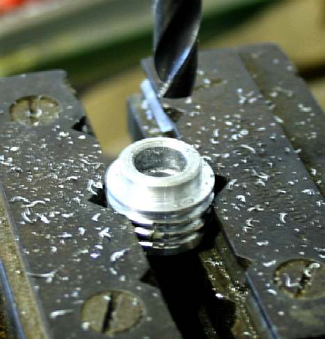
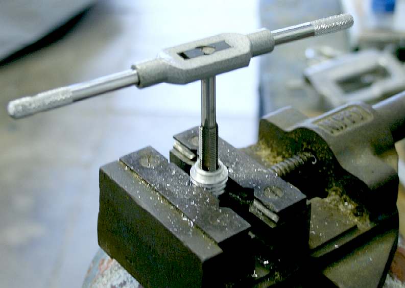
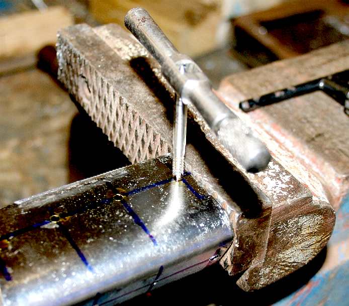
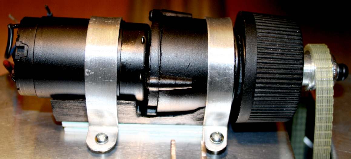
POWER TRANSMISSION - It is important to have the correct drum speed and torque. On a limited budget we raided our electrical and mechanical spares boxes to find motors and gearboxes that might be suitable. The matching alloy pinion from a power plane had to be re-engineered to fit our motor/gearbox solution. We'd normally use a lathe to ream out the old thread on this cog, but it had a machined flat end, so could be fixed in our 'Nippy' pillar drill vice. A quality tungsten steel tap was then used to cut a fine metric thread. A lathe would give us slightly better results if this was a precision high-speed assembly, but in fact the machined cog fitted to this unit as it came off the factory line, was not running 100% true anyway. Something that the manufacturers might note. In other words, we'd do better making our own cogs. A pillar drill is also a useful tool for tapping an accurate thread.
We found several beefy dc motors, from 6-24 volts - all of which could have done the job with suitable controls. We also found a number of gearboxes that fitted the bill, but eventually settled on an epicyclic gearbox from a hand-held cordless drill. Robot engineers love epicyclic gearboxes for this reason.
EPICYCLIC GEARS - Planetary gear trains provide high power density in comparison to standard parallel axis gear trains. They provide a reduction volume, multiple kinematic combinations, purely torsional reactions, and coaxial shafting. Disadvantages include high bearing loads, constant lubrication requirements, inaccessibility, and design complexity.
The load in a planetary gear train is shared among multiple planets, therefore torque capability is greatly increased and the gearbox is lighter. The more planets in the system, the greater the load ability and the higher the torque density, but also the higher the energy losses.
The efficiency loss in a planetary gear train is in the range of 3-6% per stage dependent on proper configuration, compared to a chain drive which loses about 2-3% per stage (98% efficient). But this type of gearbox ensures that a high proportion of the energy being input is transmitted through the gearbox for a compact unit, with comparatively low mechanical losses - provided that such a unit is well lubricated. As any engineer knows, each bearing soaks up energy and lubrication oil uses energy as it is pumped around cog teeth, but lubrication is essential.
The trade off is that an electric motor operates far more efficiently when it is spinning fast, rather than stalled, when it draws high amperages that can rapidly drain a battery. The worst drive transfer of any type of gear is a worm drive where the efficiency can be as low as 20%.
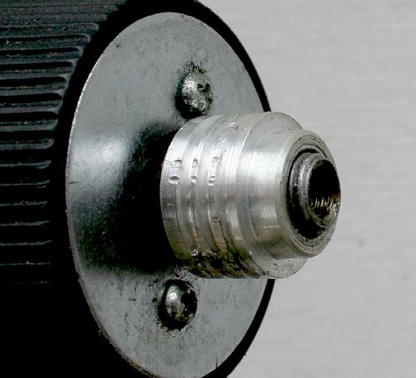
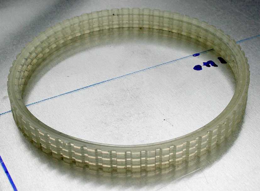
BELT PULLEYS - The simplest pulley is probably that used to drive an alternator on a car, also used on a lot of farm machinery because the belts are cheap to make. The belts used prior to about 1980 were mostly 'V' shaped in section, running in a 'V' in the pulleys. On vehicles today multiple grooved belts are used for increased life and efficiency, where such belts are more flexible and because of the increased contact area, can carry more load for the same occupied space. When greater loads need to be transferred, such as from a crankshaft to a camshaft on a petrol engine, a toothed belt is preferable and more efficient, losing around 5-8% in the process - but then all rotational energy transfers cause an energy loss. Even the simple connecting rods on old steam locomotives.
Pulleys are locked onto the shafts of rotating machinery using slots cut into shafts, square ended mountings and lock-nuts. The smaller pulley seen in the left hand picture above screws onto the shaft using a conventional clockwise thread, with a centre screw that is threaded counter-clockwise, so being self tightening, to prevent the pulley coming off.
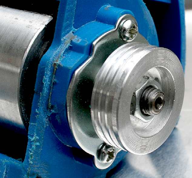
MKI TEST RIG - ABOVE on the left is a ribbed belt that is also toothed with a thick outer rim. This belt is designed to carry loads of 600 watts for a power plane and to cope with high-speed jams. It is more than capable for our purposes. On the right is the modified housing from a power plane. We've blanked off the usual exhaust/extractor side tube with an alloy cap and machined two fresh exit holes that line up with our transfer tubes. The blue casing is made of a very strong reinforced ABS plastic, which in this case is a joy to work with.
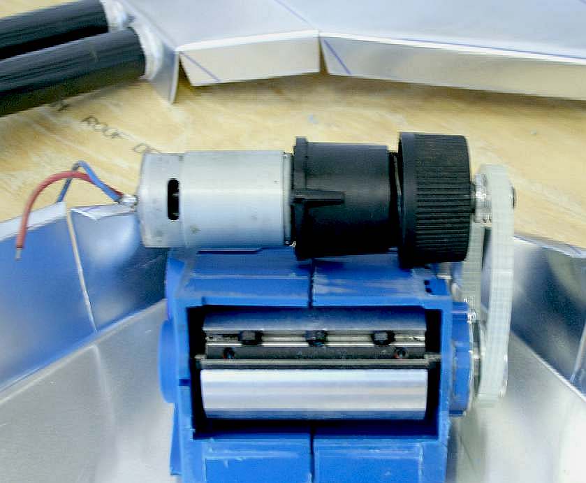
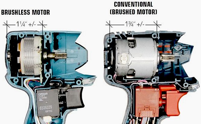
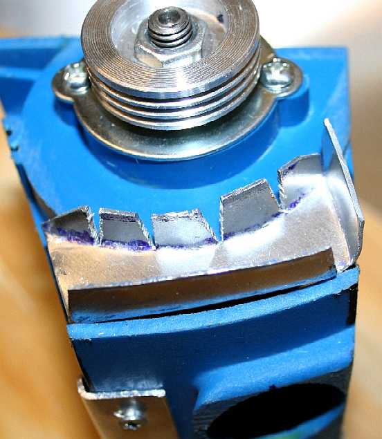
SHREDDING MILL - The shredding mill is the first stage of filtration in this experimental suction head. That is because we've skipped a couple of stages upstream and downstream, just to be able to demonstrate the principle for potential backers to be able to see for themselves, the robotic vacuum cleaning boat in action. At this stage it does not matter that there are no safeguards or that the head is not as efficient as it might be when technically fully loaded and specifically designed to deal with a large variety of plastic waste. This setup is not the ideal, but it was cheap to make. Roboteers will immediately recognize the cordless drill motor and transmission. The brushed motor shown here (above & below) is to be replaced with a brushless motor that is waterproof. In the pictures elsewhere on this page you can see the gear components of the innocuous looking black housing in between the motor and belt drive cog.
The mill as it is shown here would be useless without the guides and static steel striking plates against which the tungsten blades can work, without harming the plastic housing or alloy suction head. Bear in mind that this is only a 'proof of concept' project. We are not designing this boat to cruise for years on end without attention.
WOODEN MOTOR MOUNT - The mill motor will be cushion mounted in this treated softwood cradle. Two metal straps will pass over the motor and mount and screw into the steel of the base to hold the drive solid. Drive belt adjustment may be effected by inserting shims. Belt stretch is not anticipated with the low level of use this model will see. The wood is to be sealed, primed and painted matt black.
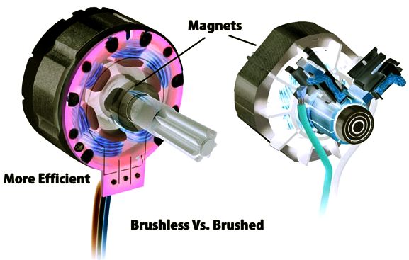
WHY
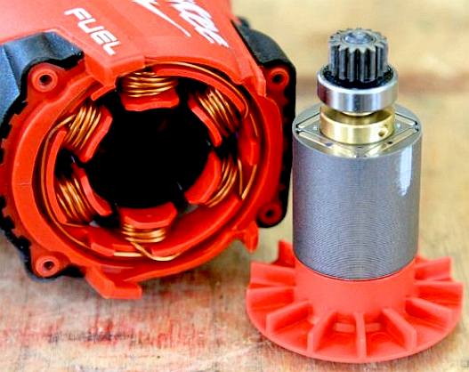
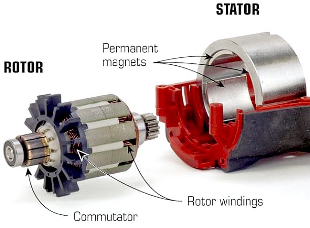
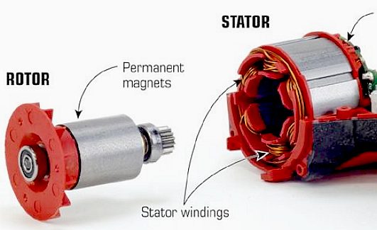
BRUSHLESS MOTORS? - A brushless motor loses the brushes and the commutator and the locations of the magnets and windings are reversed: The magnets are on the conventional motor shaft and the copper windings of the armature are fixed and surround the shaft. Instead of brushes and a commutator, a small circuit board coordinates the energy delivery to the windings.
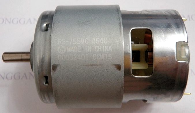
Brushless motors are typically around 80% efficient, brushed motors such
as the Mabuchi
unit shown above are nearer 50%.
In addition, brushless motors can be more powerful overall. Because the copper windings are on the outside of the motor configuration, there is room to make them larger. Brushless motors also don't have the friction and voltage drop that brushes create by dragging against the spinning commutator. This physical contact results in a continuous energy loss during the operating process.
PERMANENT MAGNET MOTORS - Power and space are at a premium in cordless tools, so the stators in brushed cordless models contain permanent magnets instead of windings because magnets are smaller and do not require power. Such permanent-magnet motors can be highly efficient if they contain strong rare-earth magnets. Among the qualities of permanent-magnet motors are good low-speed torque and magnetic self-braking action.
BRUSHLESS MOTOR QUALITIES -
A number of tool-company engineers and product managers were interviewed to get their take on brushless cordless tool motors.
The one thing that everybody agreed on is as follows.
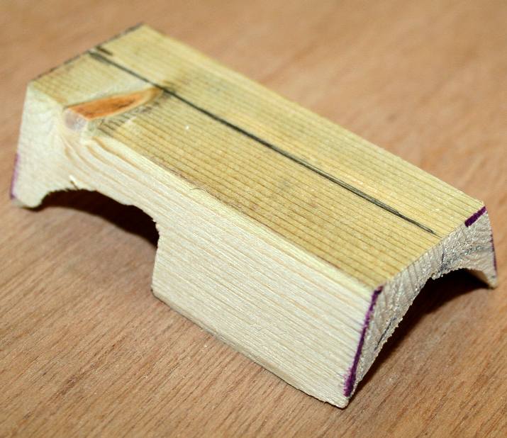
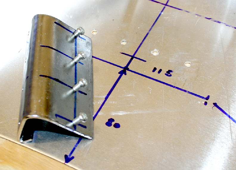
SHEET METAL FORMING - There is no magic to making large or small parts accurately - it is down to the marking out and cutting skills of the fabricator - unless you have CAD-CAM, laser cutters, etc. The same cardboard template formula works in miniature. We needed to make another blanking plate for the other end of the mill. This time it was not round, so would be a trickier operation, but, provided the measurements are marked correctly, and the craftsman has some experience of forming parts from sheet metal, anything is possible. The blank on the left is marked out roughly using a cardboard template and cut ready for more folding. The outer rim is beaten to form a large diameter radius and folded over with a planishing hammer. The inner diameter tabs are then folded up and a step formed on one side to match that in the ABS mill housing. The alloy component is then drilled to accept hardened steel screws, for fixing.
PLASTIC MILL BLANKING PLATE - The partly formed plate is offered up to the slot into which it must be a tight fit. It is far too large at this stage and must be adjusted (fettled) until it fits perfectly. Use pliers with smooth jaws to make rough corrections, then beat with small hammers and finally file the edges so that the plate sits inside the housing to create a water tight fit.
SCREW FIXINGS - When you are happy with the seating, the plate can be screwed into place. Only three screws were needed in this case as the fit was so good (an interference fit), that it was extremely difficult to remove the plate to be able to drill the plastic housing for the fixing screws. It did not need fixing screws, but better safe than sorry.
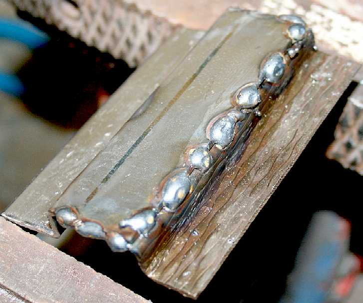
We'll be dealing with the static steel striker plates next. The rotating drum will work plastic against the steel striking plates, as it chops it into small pieces. The clearance between the steel plate(s) to the tungsten blades determines the size of plastic that is allowed through to the next stage of filtration. The full size ship will use a more sophisticated shredding arrangement - but the concept is similar in principle. The mill housing has been reinforced with alloy plates, clips and clamps and will be further beefed up with chrome steel mountings. These parts are not shown above.
SAFETY SCOOP and SCREENING
We don't want animals such as fish or marine mammals entering the system. That means installing sensors and warning systems, and finally, if an animal ignores such admonition, a shut off fail safe. Unavoidably, some smaller organisms will get through and may become a casualty of ocean waste, the design brief is to keep potential casualties to an absolute minimum.
AUTOMATION - Machines can be programmed to operate intelligently. The SeaVax project is an opportunity to open up robotics to new fronts. Just about everything on this ocean going vacuum cleaner is electric, meaning that the systems can be controlled relatively easily. Micro computers that are more than capable of running onboard ship systems are cheaply available for students to learn how to write control software at an early age. Such computers are the venerable Raspberry Pi and Arduino boards. Our quest is to KISS everything with the magic simplicity stick, where complication can lead to operational problems.
COMPUTING
POWER - The Apollo Guidance Computer (AGC) was a digital computer produced for the Apollo program that was installed on board each Apollo Command Module (CM) and Lunar Module (LM).
This computer had 100s of times less computing power than the Raspberry Pi
shown above. The AGC provided computation and electronic interfaces for guidance, navigation, and control of the spacecraft. The AGC had a 16-bit word length, with 15 data bits and one parity bit. Most of the software on the AGC was stored in a special read only memory known as core rope memory, fashioned by weaving wires through magnetic cores, though a small amount of read-write core memory was provided.
COMPUTER MINI HISTORY - By 1959 discrete transistors were considered sufficiently reliable and economical that they made further vacuum tube computers uncompetitive. Computer main memory slowly moved away from magnetic core memory devices to solid-state static and dynamic semiconductor memory, which greatly reduced the cost, size and power consumption of computer devices. Eventually the cost of integrated circuit devices became low enough that home computers and personal computers became widespread.
Third Generation computers generally relied on Jack Kilby's invention of the integrated circuit (or microchip), starting around 1965. However, the IBM System/360 used hybrid circuits, which were solid-state devices interconnected on a substrate with discrete wires.
PERSONAL COMPUTERS (PCs) - The advent of the microprocessor and solid-state memory made home computing affordable. Early hobby microcomputer systems such as the Altair 8800 and Apple I introduced around 1975 marked the release of low-cost 8-bit processor chips, which had sufficient computing power to be of interest to hobby and experimental users. By 1977 pre-assembled systems such as the Apple II, Commodore PET, and TRS-80 (later dubbed the "1977 Trinity" by Byte Magazine) began the era of mass-market home computers; much less effort was required to obtain an operating computer, and applications such as games, word processing, and spreadsheets began to proliferate. Today, we could not do without computers in the workplace.
GRIST TO THE MILL - The plastic mill needed a stator/reaction cutting plate and mounting. The solution was to make a plate from steel that is strong enough to take a continuous beating as plastic solids are shredded against it. Steel is much harder to work, especially the tight bend for the lip that hooks over the mill mouth. The plate was drilled and tapped to accept 3mm screws that would come from underneath the aluminium vacuum head/mouth.
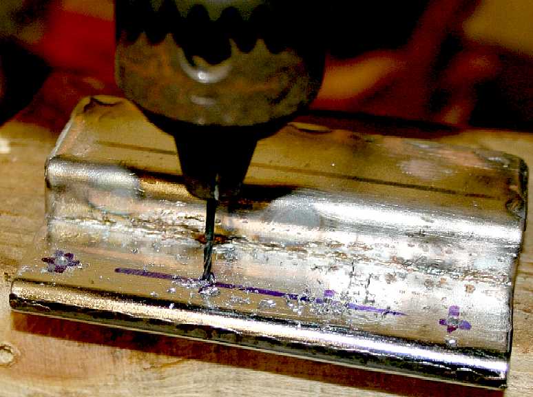
Every engineering operation is time consuming. But, there must be no shortcuts. Accurate marking out is followed by drilling in a pillar drill, going from a 1mm drill up to a 2.5mm. Matching holes in the aluminium mouth were drilled to 4mm, to allow for a little leeway in assembly. Blue marker is used as guide prior to scribing and centre punching. The more methodical you are the quicker the job will go. There are no shortcuts if you want a quality product. In fact taking shortcuts will mean having to make the item again as our work experience volunteers found out - because it will not be to specifications. You can bet on it.
JULY 2015, MK I SHREDDER MOUNTINGS - A second steel plate is shown above the mill partly folded. The marking, tapping and mounting procedure is the same. the mill will thus be mounted top and bottom with 8 x 3mm metric screws. There will be additional side/front mounting screws when the aluminium guide is fitted (not shown here). The whole assembly will be very robust - though not quite up to Robot Wars standards.
This mill cuts plastic entering the mouth at the top and at the bottom of the openings on either side of the rotating drum. In power wood planes, using similar drums, they only cut at the leading edge. How this design manages that is proprietary information. We can also reverse the blade rotation to clear blockages and purge using other means.
MK I SHREDDER MOTOR MOUNTINGS - The partly folded plate from above is matched with another chunky section steel plate, formed and welded to give a double thickness for tapping for the motor mounting clamps. The completed fabrication is then marked and drilled using a 1mm HSS drill bit in a pillar drill. These holes are matched to the mill housing being careful to take advantage of the strengths of the ABS plastic. Placing is therefore important. You will have gathered from reading these pages that engineering is a repeat process of cutting, forming, joining and machining metals.
DESIGN - is the process of thinking a process through, to not only include the working of the object being made, but also how to make the object. That is why we have production engineers as opposed to design engineers. Then we have what is known as a conceptual designer. A conceptual design engineer imagines a product and process first of all. The feasibility of turning a concept is all in his mind. Then he turns that idea into a working demonstrator. This kind of (virtual) abstract creativity is rare. Whereas, gradual improvements on an existing design is not so demanding in concept, but still time consuming.
Take the modern motor car. It has been evolving every year with thousands of engineers around the world making minor changes every time a new model is released. These changes are improvements to the design. It is a form of man-made evolution. Just imagine if the first car designer had built the perfect vehicle the first time around. You'd only ever need to buy one car for starters. As we write this article, only one conceptual engineer is looking at improving this design, with two others being Devil's advocate. Though, now you have read about it, you too can begin to think on ways to improve the concept.
MK I SHREDDER MOTOR MOUNTINGS - The steel motor mounting plate is screwed to the ABS mill housing. The holes for the motor mounting clamps are not yet drilled. The steel plate is though primed and painted. On the full size ship, components such as this are likely to be made of 316 marine grade and above super-austenitic stainless steel. Even 316 grade can pit in areas where water is relatively still. This is a major problem where bolts are used in seawater.
Stainless steel is 100% recyclable. An average stainless steel object is composed of about 60% recycled material of which approximately 40% originates from end-of-life products and about 60% comes from manufacturing processes. According to the International Resource Panel's Metal Stocks in Society report, the per capita stock of stainless steel in use in society is 80–180 kg in more developed countries and 15 kg in less-developed countries.
VACUUM HEAD INNER GUIDE - The hydrodynamic fluid flow of this prototype head is a minefield for our technicians. To reduce pipe friction to a minimum, hence the amount of energy used to process the plastic from the ocean, fluid flow should be as linear as possible. That is difficult where round pipes are used on this development model. On the other hand, it is impossible to keep the water flow linear when using a hydro-cyclone, that is by definition incredibly energy sapping.
By the same token, the large frontal area of the vacuum head would normally make a vessel inoperable. Drag (kilograms of force preventing forward motion) is a product of area multiplied by form, multiplied by the density of the liquid medium. The manta ray and many other filter feeding fish have their form design down to a fine art. That has taken millions of years of evolution as nature perfectly adapts a shape and function to fill an ecological niche. We don't have that long, or the plastic in the oceans will not only poison the fish swimming in the garbage gyres, but could also poison the humans that put it there.
CARDBOARD - Once again, it is good practice to make a test development in cardboard. Especially where the inner guide is fitted at an angle - and there is a gentle funnel like slope on the outer skin as solid plastic is shown the way to the rotating mill that will take it down in size for us to be able to filter out and store until the holding tanks are full. Please don't try this at home, and if you really must, then watch your fingers!
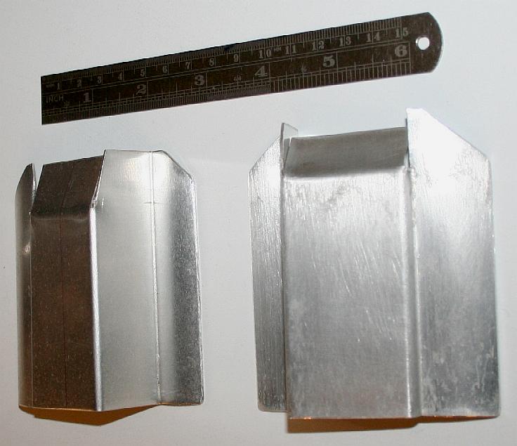
VACUUM HEAD INNER GUIDE - Here is the alloy panel cut and folded. That's the easy part, then it has to be fitted and you can be sure it will not go in as easily as the cardboard version.
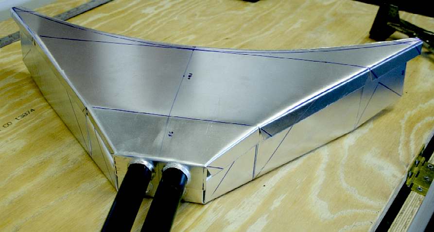
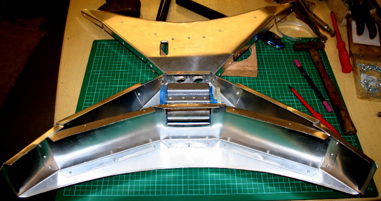
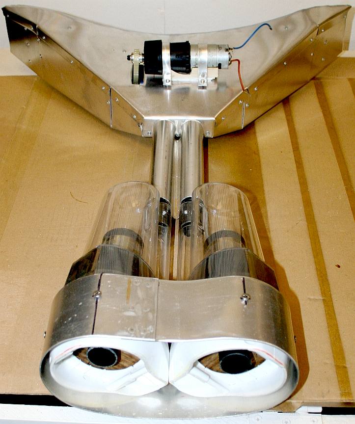
OCEAN SWEEPER HEAD - The alloy inner guide is pop riveted to the lower section of the ocean sweeping head. The upper section, or cover, is screwed in place because of course we have to be able to access the mill for servicing, measurement and other data collection. We are already working on a more hydrodynamic version of this head, but we need to test this one to create a baseline from which to be able to measure improvements. The more efficient the operation of a collection head, the more plastic can be removed from the ocean each day, using only energy from nature. As a design exercise, balancing up all the variables to make a workable solution is the challenge. All workboat designs are a compromise, but pushing a giant vacuum across an ocean again and again is something else.
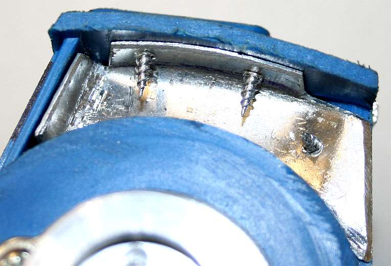
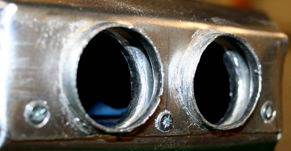
VACUUM HEAD FEMALE PORTS - This is the rear, or exit ports from the ocean sweeping head after the plastic grinding mill. Twin tubes feed shredded plastic into the cyclonic chambers from these exits. Note that there are two skins, with one aluminium skin domed outward and the inner skin domed inward. This gives the tubes a large surface area to spread loads. The tubes are structural components in the raising and lowering of the suction head.
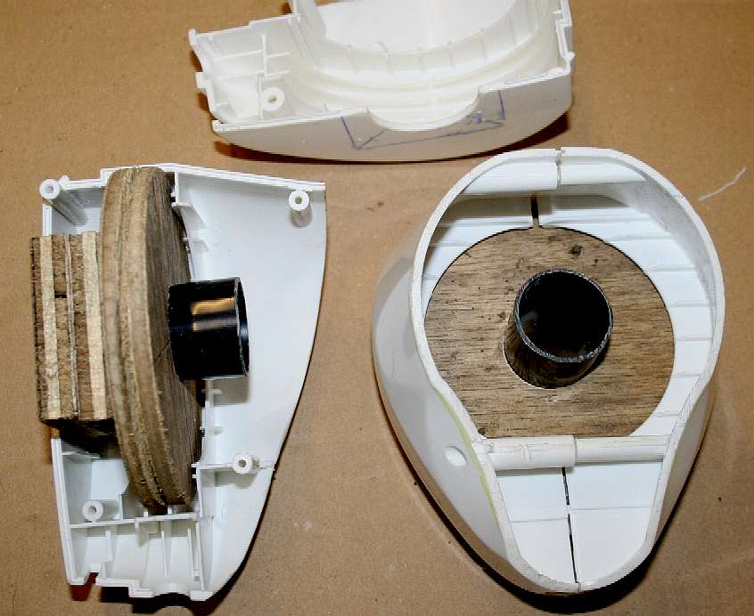
MODIFICATIONS - The ABS plastic housings needed to be modified to deal with water rather than air. Plywood inserts were made that would reinforce the structure and accept the pipes that would mate with a high quality flexible silicone tubing. The idea being that the fit of the tubing would be good enough without the need for securing clips - meaning we could assemble and disassemble more easily during water trials. The plywood was sealed and bonded into the ABS casings as these parts would never need to servicing, apart from cleaning the inside of the plastic transfer pipe.
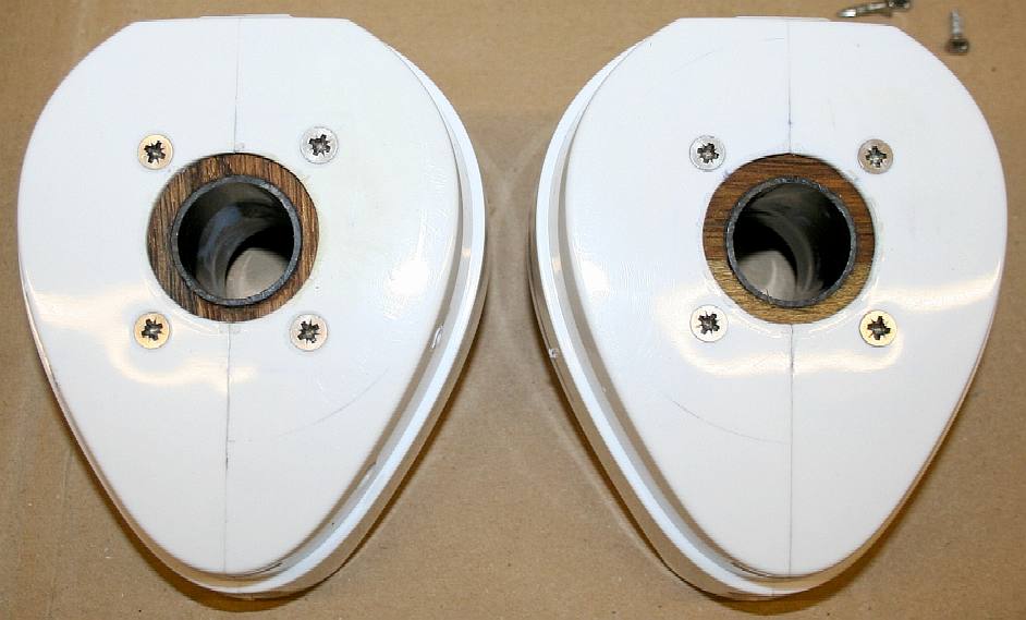
HEADS UP - This is what the two units looked like when assembled. Four stainless steel screws through the ABS casings into the plywood inserts, beefed up the original casing fixings that were weak in comparison. Over engineered maybe, but rather that than have problems when out in the field.
MILL & FILTRATION - In this photograph you can see the motor mounted in the wooden cradle during a test fit. Apart from painting, the mill motor will have a waterproof protective casing to keep water away from the motor during shallow operations. Eventually, we'll replace the brushed motor with a sealed brushless motor for deeper water (submerged) trials. Note how the ABS casings fit snugly inside the oval aluminium frame that unifies them.
MOTOR MOUNT - The mill motor is seen here screwed in place and painted in matt black. When we are sure that we don't need a torque limiter, we can lock the clutch. In robotic circles this is known as a hack. The whole unit will have a fairing that will keep the mechanicals and electrics in a bubble and prevent any leakage of ground plastic. We have used one of these motor/gearbox assemblies to power the jaw closing on a giant robot hexapod.
EXTENSIONS - Two brackets are needed in 16 gauge ally to allow use to reposition the filtration heads. We found it extremely difficult to connect up the silicone vacuum piping with tight curves as the wider pipe centers needed to narrow for the hull entry points, so decided to make that a much less arduous task, while also improving other fluid flow aspects. In the picture above you can see that we made a cardboard template first, and once satisfied with the bends, etc, made and folded an aluminium version for the port hinge. The starboard bracket is marked ready to be cut in the picture above.
EXTENSION BRACKETS - Port and starboard brackets cut and formed. They are as near as possible mirror images of each other. Our craftsmen take their time when shaping metal parts, and then fit them with the same care and attention to detail. The next stage is to drill holes to either rivet or screw these parts to the aluminium oval frame.
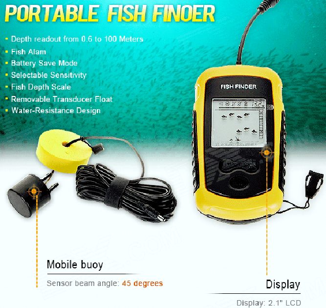
SONAR FISH FINDER - The above instrument may prove to be sufficient for our "proof of concept" purposes. We can link the alarm function to a cut-off trigger as a first response. We might then link these triggers to our collision electronics, but then we'd need two sensor heads to be able to determine in which direction the boat should be turning to avoid a school of fish - in our case most likely minnows. The steerage collision avoidance system will take priority over the fish avoidance system. Sorry fish, but the boat is expensive and a fish cannot sue you for negligent navigation at sea.
INFRA RED - Over short distances, even clean water absorbs red and infrared light strongly, with intensity dropping exponentially I=I0e−αx, and α being in the vicinity of 0.01−0.1cm−1 (depending on frequency). This might be a problem for model receivers where it is ok getting an intensity which is, say, 1/100 of the normal intensity, you could calculate a maximum distance between receiver and transmitter being perhaps 0.45 – 4.5 meter (depending on the frequency). If the receiver is only a tenth of that sensitivity, you can halve those distances. But, this general rule means that for our SeaVax proof of concept model, we might use infrared sensors to detect some fauna.
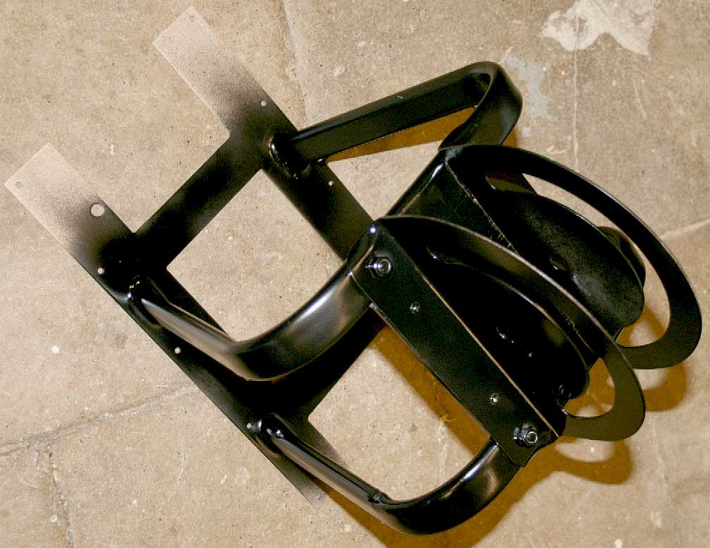
CRADLE & SWIVEL - The cradle assembly seen above is part of the revolving display stand for Innovate 2015. The ocean cleaning cyclonic chambers pass through the cradle, while the base plate holds the proof of concept model firmly. This is upside down in the picture above.
SEAVOLUTION
The final configuration is guaranteed to be very far removed from anything that we publish before IP rights are applied for. We can say that because the design has already evolved significantly, as we have identified and overcome problems that could not possibly have been anticipated, save for experimentation, compared to our first jottings from January 2015.
LINKS
Waste Management World waste-to-energy-industry-welcomes-consultation-on-plastic Fast Coexist James Dyson is designing a giant vacuum on a barge to clean ocean trash Kumu 2013 those crazy men and their plastic cleaning machines vafusa hydrocyclone separators Vortex depollution products shredders pet bottle perforator Jenco UK granulators shredders Grabcad diy-shredder-crusher-chopper-grinder Wikipedia Apollo_Guidance_Computer Wikipedia History_of_computing_hardware Robot marketplace store_dewalt_gearboxes gear solutions article epicyclic gearing a handbook Toolmonger 2012 October Dewalts brushless impact driver The Star diy 2012 a_great_innovation_in_cordless_power_tools Tools of the trade cordless drills brushing up on brushless motors https://en.wikipedia.org/wiki/Stainless_steel http://www.toolsofthetrade.net/cordless-tools/brushing-up-on-brushless.aspx http://toolmonger.com/2012/09/17/dewalts-brushless-impact-driver/ http://www.thestar.com/life/homes/diy/2012/06/01/a_great_innovation_in_cordless_power_tools.html http://www.speedace.info/internal_combustion_engine.htm http://www.robotmarketplace.com/store_dewalt_gearboxes.html http://www.gearsolutions.com/article/detail/5837/epicyclic-gearing-a-handbook https://en.wikipedia.org/wiki/Epicyclic_gearing http://www.solarnavigator.net/alcan_aluminum_alloys.htm https://en.wikipedia.org/wiki/Aluminium https://en.wikipedia.org/wiki/History_of_computing_hardware_%281960s%E2%80%93present%29 https://en.wikipedia.org/wiki/Apollo_Guidance_Computer http://www.caterpillar.com/ http://www.jcb.com/ http://www.staedtler.co.uk/ http://grabcad.com/library/diy-shredder-crusher-chopper-grinder http://www.jenco.co.uk/granulators-shredders.htm http://www.dragon-machinery.co.uk/products_shredder.php http://www.vortexdepollution.com/products/shredders/shredders/pet32-perforator http://www.forrec.eu/dual-shaft-shredders http://www.machinerydata.com/PlasticLumber.htm http://www.ksb.com/giw-en/ http://www.hydrocyclone.com/ http://en.wikipedia.org/wiki/Hydrocyclone https://www.vafusa.com/hydrocyclone-separators.htm http://kumu.cc/2013/03/27/those-crazy-plastic-cleaning-machines/ http://www.dyson.co.uk/ http://news.nationalgeographic.com/news/2014/04/140414-ocean-garbage-patch-plastic-pacific-debris/ http://www.unep.org/environmentunderreview/
Youtube gears in motion
Cofine machinery is a hi-tech company and professional research development company concerned with Plastic crushers, shredders and Plastic Granulating Machines:
Tel:0086-512-58662047 http://www.cofinemachine.com/
Our love affair with plastic is choking the oceans. Once people know about it, they want to stop it. But how? The next question is who? Obviously, if any of the researchers involved so far had come up with a solution, they would have sorted it years ago. We are a practical think-tank fresh to the issue and without a budget. We hope to be able to collaborate with other marine organisations that are funded for this work, or who have funds to investigate viable projects. You cannot donate to us directly on this site, but we hope to identify partner sites shortly where you can support a project much like that proposed herein, or better still, our own practical experiments. Volunteer Careers.
ACIDIFICATION - ADRIATIC - ARCTIC - ATLANTIC - BALTIC - BERING - CARIBBEAN - CORAL - EAST CHINA ENGLISH CH - GOC - GULF MEXICO - INDIAN - IRC - MEDITERRANEAN - NORTH SEA - PACIFIC - PERSIAN GULF - SEA JAPAN STH CHINA - PLASTIC - PLANKTON - PLASTIC OCEANS - SEA LEVEL RISE - UNCLOS - UNEP WOC - WWF
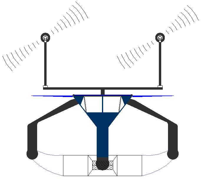
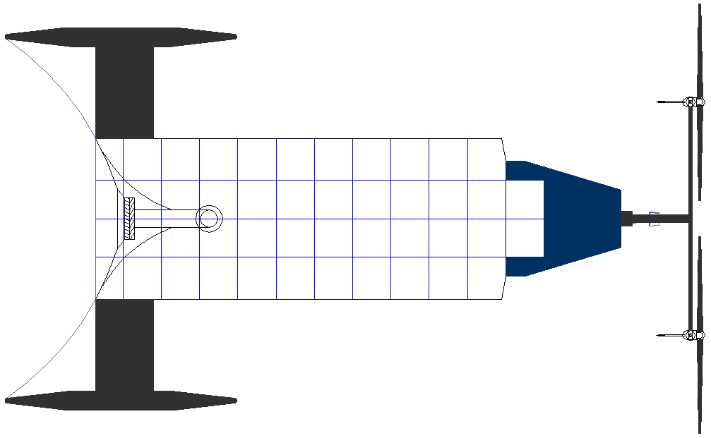
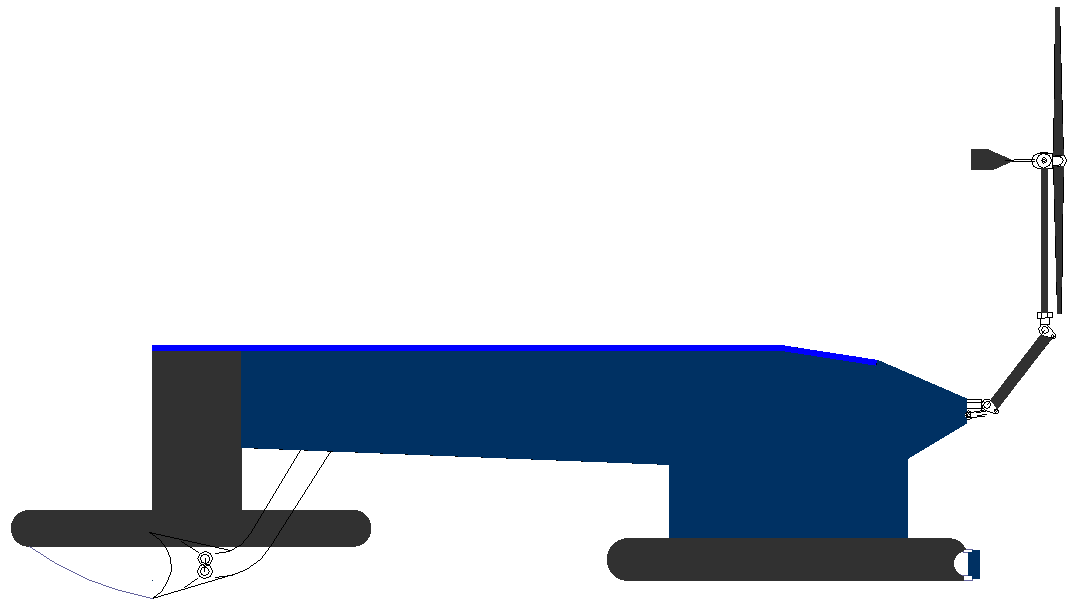
SEAVAX DRONE JANUARY 2015 - Head-on view of the ocean going mobile cleansing unit. The design of the scoop and shredding head is all important if these robotic machines are to be efficient. This is a draft proposal for a design that is cost effective and yet still a practical vacuum-pump based ocean sweeping ship.
Solid waste is moved into a large holding bay after treatment and compression, then stored until it can be off-loaded onto transport barges. In this way the specialized cleaning robots can work more or less continuously.
The ship carries two large wind turbines that generate electricity in combination with deck mounted solar panels (shown here in blue) to power the onboard machinery. Processing takes a lot of energy, calling for a very high output mobile generator - which is what the patent ZCC concept is all about.
A SeaVax would operate best using a fleet search program called SeaNet, an example of which is seen on the SeaNet page.
JANUARY 2015 - Plan view of the SeaVax concept, showing the basics of the shredding head and scoop that funnels plastic garbage towards the rotating cutters. A SeaVax is basically a solar powered vacuum cleaner, except that the brushes that are normally used to sweep a carpet, are replaced with steel shredding drums that are specially designed to cope with plastic bottles, bags and rope. There is nothing available off-the-shelf, unfortunately. As mentioned above, this is uncharted territory design-wise.
EARLY DAYS - Side view of the earliest SeaVax concept showing the scoop head and lead in guides that funnel plastic waste to the shredding mill. This design was the subject of ongoing development leading to the current configuration. Some drawings may not correspond with earlier versions. The only thing stopping us from building a working full size prototype is funding. We'll prove the concept first in 1/20th scale before progressing to a full size prototype. 2016 may be the year that sees some serious effort to clean up our oceans.
|
||||||||||||||||||||||||||||||||||||||||||||||||||||||||||||
|
This website is Copyright © 2015 Bluebird Marine Systems Ltd. The names Bluebird™, Bluefish™, Miss Ocean™, EuroStation™, SeaNet™, SeaVax™ and the blue bird and fish in flight logos are trademarks. CONTACTS The color blue is a protected feature of the trademarks.
|