|
ECOSTAR DC50 (BE4) - SUSPENSION
|
|
|
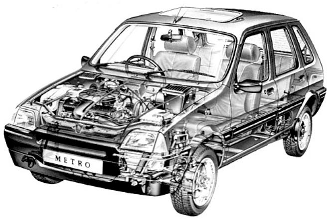
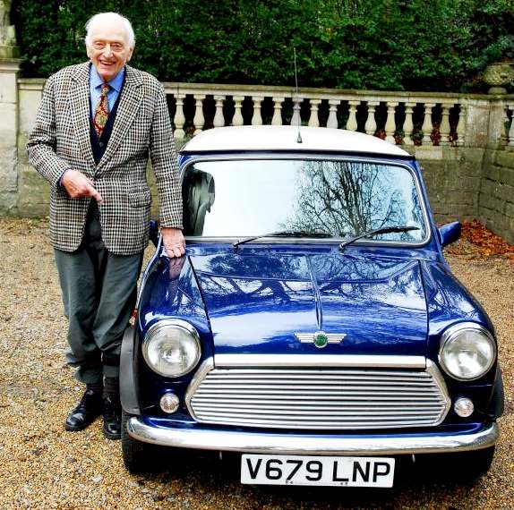
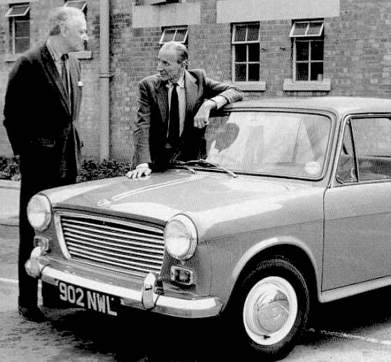
We are great fans of the VW principle, that every man should be able to afford a car. In fact that was Hitler's plan, where VW stands for "peoples car." Even a real baddie can have good moments. Prof. Porsche came up with a superbly simple design in the Beetle, that is unfortunately not suitable as an EV donor. The Metro above turned out to be just the ticket.
The rules for the Cannonball ZEV International Runs are simple, you must use production vehicle running gear - the car must be road legal. The ultimate prize is the Blue Bird World Cup. Our unique DC50 car began life as an Austin-Rover Metro. These cars used rubber cone and compressed gas suspension units with cross-axle liquid exchange known as Hydrolastic, or Hydragas suspension.
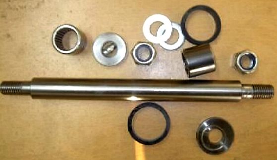
When servicing suspension bearings and joints using the rubber cone (hydrolastic) and hydragas system(s) it is necessary to de-pressurize the fluid to effect replacements. The UK team want their vehicle to be in tip-top condition so will be servicing the suspension roller bearings and spindles along with other brake and steering parts.
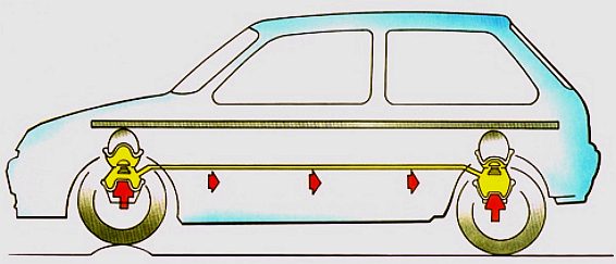
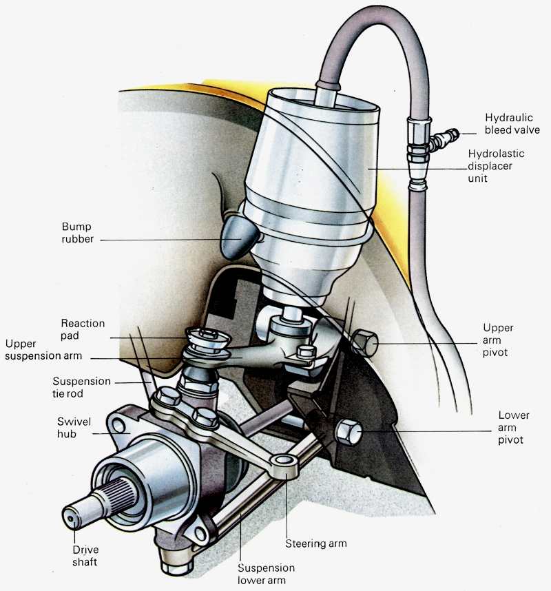
This is the basic suspension layout of the Metro, actually this is a picture Mini subframes. But they are very similar and of course the Metro was derived from the Mini design, an evolution rather than the Mini revolution. The Mini being the most popular car ever produced in the UK, with over 5,000,000 million cars sold worldwide. The Rover Metro's Hydragas suspension has sealed hydraulic displacers, one at each wheel connected on each side of the car by a reinforced plastic pipe. When a front wheel hits a bump, the upward force is transmitted to the fluid in the lower diaphragm. This in turn transmits the pressure to the gas in the upper diaphragm, which compresses to absorb the shock. At the same time, fluid is forced through the pipe to the rear unit. The result is that the floorpan stays level: the front end doesn't lift and the back end doesn't squat. At the same time, the redesigned geometry helps to prevent dive and lift on braking and acceleration, giving an impressively smooth, level ride.
ABOUT
- HYDROLASTIC v HYDRAGAS
Both are suspension systems rather than just springs, in that they include a damping system to slow the action of the suspension. The operation of both systems is the same, operating in the same dimensional space. Thus, they are interchangeable.
The
main objective of using fluids, is to hydraulically link the front to the
rear, to provide a more level ride. The smoother the ride, the less energy
the car will need to drive it along the tarmac.
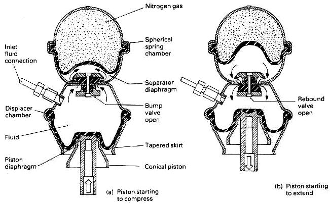
In this diagram the left unit is uncompressed and the right compressed.
There are two containers for each unit as seen in the diagram above, stacked on top of each other, with the nitrogen gas (spring) above the fluid filled chamber below.
The
lower chamber is linked hydraulically to the fluid chamber at the opposite
end of the car. In order to flow to another unit, the fluid has to flow through a valve assembly between the two containers, and then through a
long pipe to the other unit.
The front hydragas unit is compressed by a bump, sending fluid to the rear which caused the swing arm to push down - so lifting the car by the same amount as the front wheel goes up - canceling out the bump. Some of you may have noticed the opportunity that such a system provides in terms of micro energy generation. This would not have occurred to Moulton or Issigonis, because of course their cars were petrol powered. Ours is electric with a battery store as a load leveler. See the example micro generators at the foot of this page - all of which are too large for this application.
The next question is; what happens if both front and rear units are compressed at the same time, when they'd cancel each other out? The answer is that the top containers of each unit have a spring inside them - rubber on the hydrolastic system and gas in the hydragas units. With the lower containers being squeezed by the suspension, and no way out of the upper containers (as in escape to the other end of the car) the fluid's only choice is to compress the spring, giving pretty much the same suspension action as if the spring itself was being compressed directly.
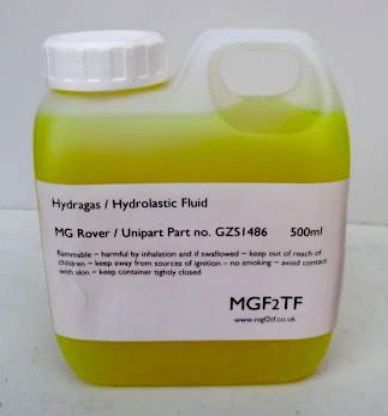
Why doesn't the fluid itself compress? That is because of a basic law of physics that says a fluid in incompressible. Of course we don't want it to compress, so it's made up or water (mostly) with some anti-freeze and anti-corrosion agents added. Coloring is added to help show up leaks or contaminated fluid easily.
The reason nitrogen gas is used, is because it is an "inert" gas - it is stable and does not react with most things, nor pressure or temperature. A compressed gas spring gives a rising-rate performance, too, just like a rubber spring.
LEFT - Front and RIGHT - Rear hydragas suspension diagrams showing the detail of the wishbones and swinging arm design. It all looks so simple and it is, but it took a lot of working out how to produce a suspension system using rubber (to begin with) and fluid.
Both systems are designed to be fit-and-forget parts or sealed units. History has shown that they have a working life in the region of 15 years and more before leakage and corrosion become issues. They provide an excellent quality of ride without compromising handling, and, providing the damping is set up correctly, don't "wallow" under cornering, braking and accelerating. The continued development of hydragas eventually led to fully cross-linked systems joining both the left and right sides together to make the most of the benefits.
Today, there are more modern systems that can outperform hydragas systems, but at greatly increased cost, and this level of performances was achieved over four decades ago, with relatively basic mechanical parts that lacked any kind of "active" or feedback control on them. Imagine how good they could be if they were active? We'll stay with what works for now, because the design outperforms most production cars today. There is no point re-inventing the wheel when there is more work to do on the EV drivetrain.
THE INVENTORS
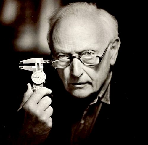
Dr Alex Moulton
Alexander
Eric ("Alex") Moulton CBE, FREng (9 April 1920 – 9 December
2012) was an English engineer and inventor, specialising in suspension
design.
The combination of conical rubber springs and small wheels was one of the many innovative developments that allowed Issigonis to achieve the Mini's small overall size. This was later refined into the hydrolastic and hydragas suspension systems used on later British Leyland cars such as the Austin Maxi, Austin Allegro and Rover Metro, and most recently on the MGF.
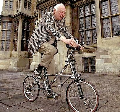
Alex Moulton with his most famous designs, the Moulton cycle with full rubber suspension and the Mini's rubber cone suspension.
Moulton also designed the Moulton Bicycle, again using rubber suspension and small wheels. Alex Moulton Bicycles is based in Bradford-on-Avon, Wiltshire, England.
Dr Moulton founded his own company, Moulton Developments Ltd, in 1956 and worked closely with the British Motor Corporation (BMC) for many years, developing automobile suspension systems. Famously, these included the rubber suspensions systems for the Mini and the Hydrolastic systems for the Austin 1100/1300 and other BMC and British Leyland models. Later, he was responsible for the Hydrogas system, which was developed for the Austin Allegro car and is still in use on the Rover 100 series and the MGF.
Alongside the development of suspension systems for cars, Dr Moulton designed his revolutionary Moulton Bicycle. He explained that this was: “… born out of a resolve to challenge and improve upon the classic bicycle …” It is said that he holds the view that “… one is capable of pursuing two main avenues of research simultaneously, but no more”. We would agree with him.
The
Moulton bicycle was the original full-suspension
bicycle, highly efficient and designed with superior performance and
comfort in mind. These bikes are lighter, safer and more comfortable, yet
still go faster than most as well! The Moulton Bicycle is now a design
classic, which has continued to be developed over many years, spawning a
massive following of devotees and a wide range of models and variants.
Dr Alex Moulton and Sir Alex Issigonis were great friends. They worked together on rubber and hydrolastic suspension - to give the UK some huge motoring successes. Sadly, the UK is backward in thinking forward on most fronts, thus surrendering a technological lead for lack of investment - the inability to predict the future such at to cater for the future is a major UK failing; part of the stiff upper lip attitude that sends pioneers elsewhere.
SIR ALEC ISSIGONIS
Sir
Alexander Arnold Constantine Issigonis, CBE, FRS, RDI (18 November 1906
– 2 October 1988) was a Greek-British designer of cars, now remembered
chiefly for the groundbreaking and influential development of the Mini,
launched by the British Motor Corporation (BMC) in 1959. Sir Alex was just
under 6ft tall with large expressive hands. He hated all things big - big
cars, big organisations, big houses - and loved to shock his listeners.
Alec Issigonis at the drawing board. He was a practical engineer who had hand built a car in plywood and aluminium for some racing success, before he went on to work on rubber suspension and the Mini motor car.
In August 1959 the car was launched as the Morris Mini Minor and the Austin Seven, which soon became known as the Austin Mini. In later years, the car would become known simply as the Mini. Due to time pressures, the interconnected suspension system that Issigonis had planned for the car was replaced by an equally novel, but cruder, rubber cone system designed by Alex Moulton.
The Mini went on to become the best selling British car in history with a production run of 5.3 million cars. This ground-breaking design, with its front wheel drive, transverse engine, sump gearbox, 10-inch wheels, and phenomenal space efficiency, was still being manufactured in 2000 and has been the inspiration for almost all small front-wheel drive cars produced since the early 1960s.
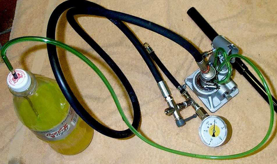
A homemade evacuation and high-pressure system based on a bottle jack hydraulic pump. You'll need a vacuum pump to complete the system. It's far cheaper than buying one of the professional systems that cost around £400.
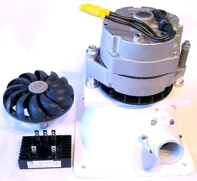
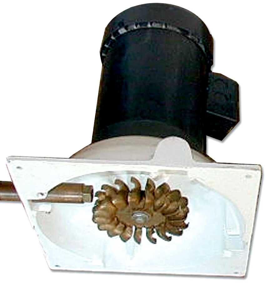
TURGO IMPULSE WHEEL - The Turgo wheel is a refined version of the Pelton. It was designed by Eric Crewdson in 1920. The maximum efficiency of an impulse wheel is achieved when the velocity of the runners at the center line of the nozzle is half the velocity of the incoming water. To achieve the highest velocities the ratio of the diameter of the wheel and the diameter to the center of the nozzle should be as small as possible. The wheel has a minimum ratio of 9:1, the Turgo has a minimum ratio of 4:1. The Turgo is half the size of the Pelton and operates at twice the speed. This makes the unit cheaper and reduces the amount of gearing necessary. The Turgo can have an efficiency of over 80% at the correct operating pressure.
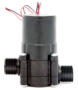
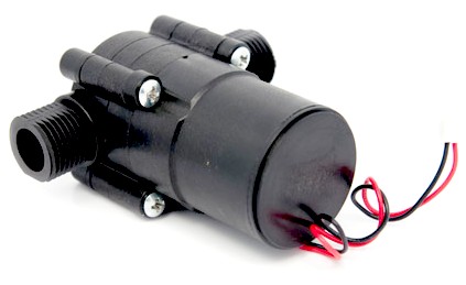
Various micro generators that are commercially available using Pelton Wheels, or variations close in design to Francis Turbines. One obvious development that would be necessary for incorporation in a hydragas circuit, is dual flow: Simply put, another nozzle aimed at the generation wheel in the opposite direction such as to work with return pressure - and give generation on the up-stroke of the car's suspension, and the re-bound. Sounds promising. All you students out there looking for a masters degree project, give us a call. Our vehicle is at your disposal as a demonstration test bed from August 2014.
AERODYNAMIC BODYWORK CONTROL SURFACES COMPETITION: BETTER PLACE - TESLA COMPETITON: SUZUKI ALTO & NISSAN LEAF MECHANICS, SUSPENSION, STEERING, BRAKES SERVICES STATION INFRASTRUCTURE SLEP - SOUTH EAST LOCAL ENTERPRISE PARTNERS
LINKS
http://www.uniquecarsandparts.com.au/how_it_works_hydrolastic_suspension.htm http://www.liquid-levers.com/psp.htm http://www.liquid-levers.com/hydravac.htm http://www.hydragas.co.uk/ http://www.horizonhydrogeneenergie.com/ Seeed Studio 36V-Micro-hydro-generator Hydro Electricity Generation Appliances http://www.seeedstudio.com/depot/36V-Micro-hydro-generator-p-634.html http://www.hydrogenappliances.com/hydro.html http://www.fch-ju.eu/news/new-website-programme-horizon-hydrog%C3%A8ne-energie-h2e http://www.fch-ju.eu/ http://horizon2020projects.com/sc-transport-interviews/storing-energy-in-horizon-2020/ http://horizon2020projects.com/sc-transport-interviews/powering-the-future/ http://cordis.europa.eu/fp7/ideas http://ec.europa.eu/programmes/horizon2020/en/ http://ec.europa.eu/transport/themes/research/horizon2020_en.htm http://www.agnimotors.com/site/ http://www.engadget.com/2012/11/13/mclaren-to-supply-ev-groundwork-for-formula-e-cars/ http://www.wired.com/autopia/2012/09/formula-e/ http://www.telegraph.co.uk/finance/The-electric-cars-of-the-future.html http://www.greencardesign.com/site/galleries/racing-drayson-b1269ev
+44 (0) 1323 831727 +44 (0) 7842 607865
Ask for Leslie Intelligent Battery Support System THE BLUE BIRDS OF HAPPINESS
|
|
|
This
website is Copyright © 2014 Bluebird Marine Systems Limited.
The names Bluebird,
Blueplanet Ecostar BE3™, Utopia Tristar™
and the blue bird in flight
|