|
|
BLUEFISH - ENERGY HARVESTING DEVELOPMENT PROGRAMME
|
|
|||||||||||||||||||||||||||||||||||||||||||||||||||||||||||||||||||||||||||||||||||||||||||||||||||||||||||||||||||||||||||||||||||||||||||||||||||||||||||||||||||||||||||||||||||||||||||||||||||||||||||||||||||||||||||||||||
|
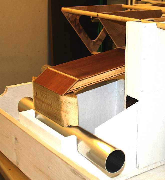
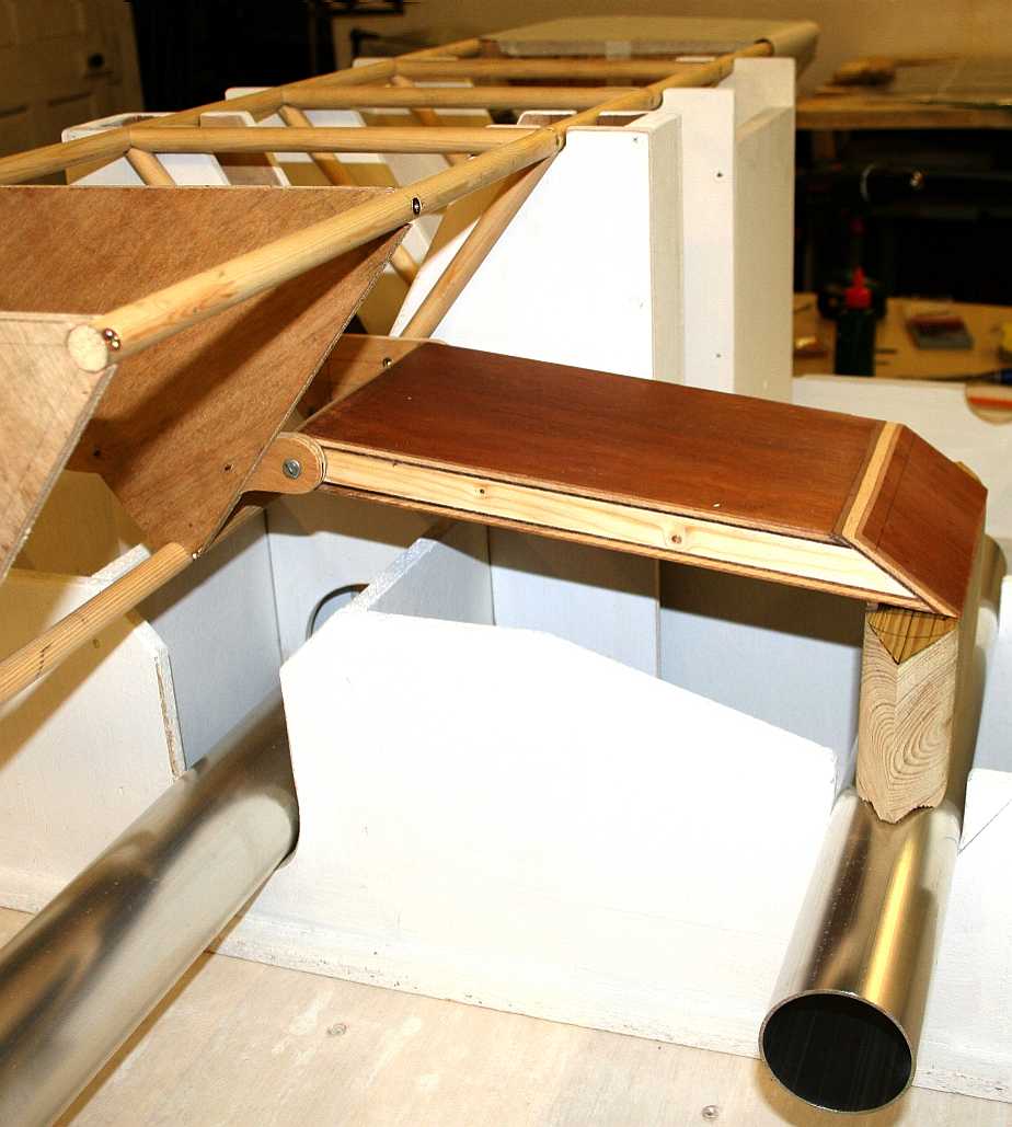
Photograph of a Bluefish active hull outrigger, looking from the front of the model. You can imagine how difficult it would have been to assemble such intricate working parts and get the angles spot on, without a jig to hold the parts in the correct position. On the full size ship the outriggers will also be the gangway used to board the vessel, load supplies and cargo. A walkway between the fore and aft cabins will be at the same height as the top of the outrigger hinges in these pictures - running inside the spaceframe.
ACTIVE HULL DEVELOPMENT
This project has now been taken over by the Cleaner Ocean Foundation and renamed the Elizabeth Swan for their climate change and ocean awareness campaigns for 2019-20.
The bluefish platform includes many live, or moving components on the vessel, one (or rather two) of which are the outriggers that stabilise the ship in crosswinds and may add to the cargo carrying capacity, if speed is not the main mission consideration.
Even with very expensive racing catamarans and trimarans, we have not seen an active, or semi-robot hull. Rather the crew of a racing sail boat usually shift their body weight and adjust the sails, swing booms, tack and other such adjustments, which classes those vessels as active, but organically rather than autonomously active (though there are now a few autonomous sailing boats in the microtransat challenge) - with robotic control being exercised by an onboard artificial intelligence. In the case of the Bluefish development program, a very simple microprocessor and program uses an actuator to hunt for speed increase by making adjustments to the angle of the outriggers relative to the main submerged hull.
Photo of the Bluefish/SNAV development model from the starboard side, showing the active outrigger hinge and leg arrangement. This is a test piece made in timber, also useful as a buck when making the same parts in aluminium. Normally, we'd go straight to alloy, but as the hinge mechanism will be the subject of experimentation, we needed to be sure it worked in principle - and it is quicker and easier to screw temporary hinge points to timber for this kind of development. Having proven the mechanism, we can then cut metal in the knowledge that it will all fit together perfectly for welding. The jig is proving invaluable - an asset to the project for models to come.
So active hulls are nothing new, only the method of controlling adjustment for maximum speed - in this case eliminating humans from the chain. And that is the theme running through the development of the Bluefish SWASH platform. We should also consider innovation here, where moveable outriggers are something new. In fact there are quite a few innovations built into the 'Bluefish' platform - a veritable collection of research parameters all in one vessel.
You don't have to keep live any one of the active components that may not be contributing to the efficiency of the hull as it deals with the elements. That is the beauty of development, use only what works, discard what does not. The main thing is to try it in the first place, and for that we need an agile mind, one that is not afraid to experiment, or is already closed off to experimentation because of preconceptions.
HULL DESIGN CONVENTIONAL WISDOM
Methods of reducing hull drag, or the barriers of the 'speed-length-ratio' are manifold, defined in several useful formulas the work of William Froude and others. The hullform we are developing does not really fit in with those well-developed theories, but they are a useful starting point.
One issue we are looking at is whether to use one balanced* foil, or two foils as a balancing mechanism. One foil would be preferable in theory, perhaps using the active outriggers as part of a balancing mechanism - but that introduces conventional formulas back into the equation, admittedly, only for two small hulls that are wave piercing, but nevertheless a retrograde step when aiming to eliminate wave drag. Wave drag is the enemy of any smallish displacement design. For that reason, and by virtue of the possibility of eliminating outrigger drag in the right conditions, we have opted for twin foils as our starting point. We may go to a single foil, to compare, if there is sufficient funding to include in a development programme.
Students of hull design may be interested in this development rather more than the robotic control element. As with the other topics covered, we will publish pictures of the active outrigger development as the build takes place. Don't forget that the prototype build is the time to try out new ideas that were not considered at the drawing board stage. Development is just that; continuous and ongoing improvement.
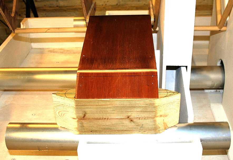
Have you ever seen a ship with hulls that move? This picture is taken from the back of the boat looking forward across the active outrigger starboard hull. The timber dowel spaceframe from 2012 will of course be replaced with an aluminium tube frame once all the parts have been test fitted and the movement proven. Working in wood is much cheaper, though there is little room for error. You cannot weld a piece back in if you make a mistake such as when working in metal. We are fortunate that our boat builder works to very fine tolerances - so rarely makes a mistake. The secret (apparently) is to measure twice and cut once.
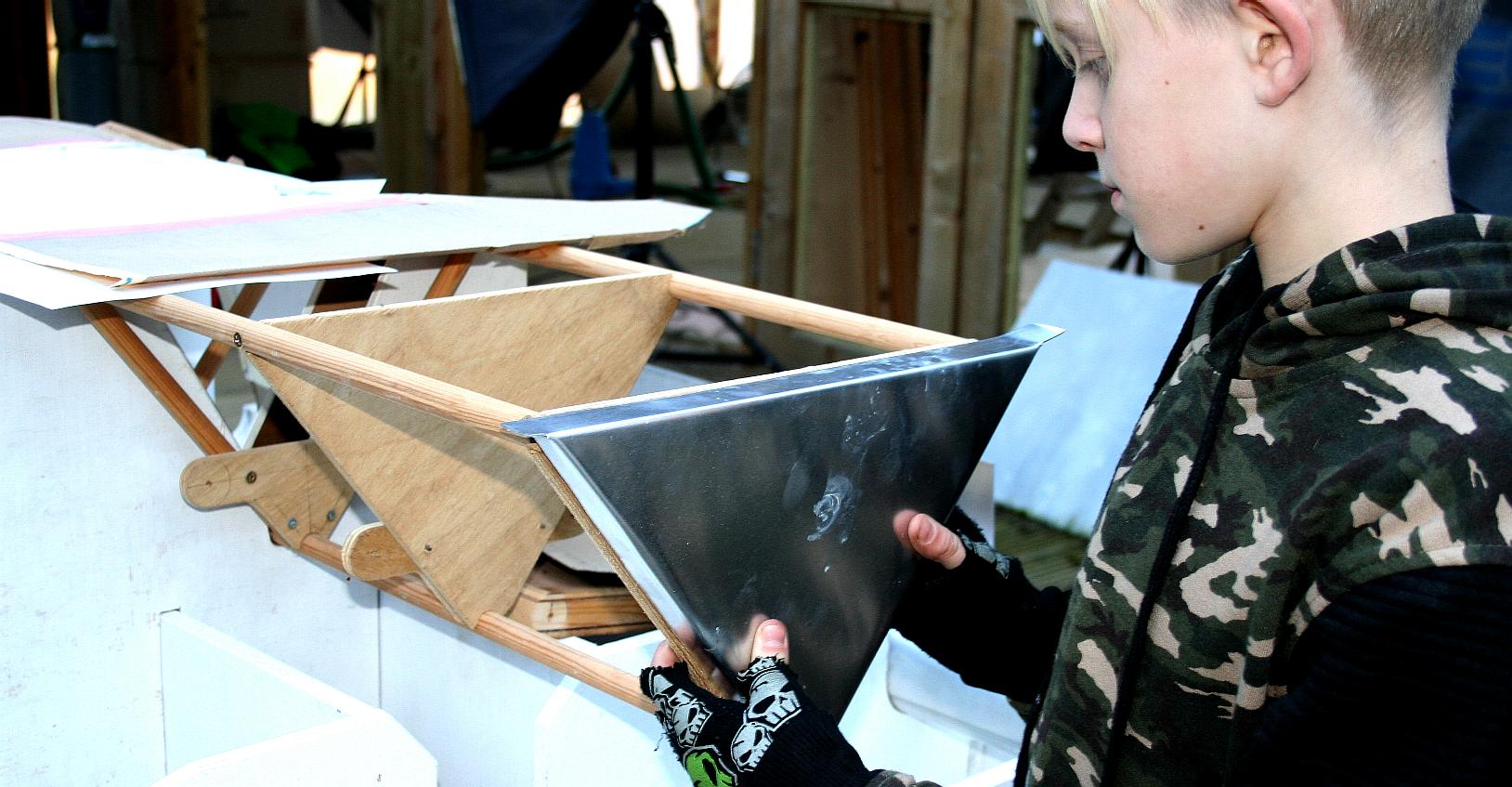
TEST FIT - The first of four bulkheads is offered up for size - and it's a perfect fit. If you make a part that is not quite right, you can fettle it a little until it slots into place. If the part is well out of tolerance, just start again and be more careful in your lofting. Copyright photographs 18 November 2018 © Cleaner Ocean Foundation Ltd. All rights reserved.
SELF RIGHTING
We have already conducted experiments on this design and we know the vessel can capsize in extreme conditions such as freak waves and hurricane winds - even where it is an exceptionally stable platform. When such conditions were induced the Bluefish hull settled at 90 degrees with one wing submerged and the other pointing skyward. The design will not invert 180 degrees, nor will it dynamically return to the upright position. A hull such as ours is a complex performance based compromise, which means we are willing to accept one weak point, to achieve the main objective - but must deal with the weakness to make a positive. Any ship can founder given the right conditions.
Because we know this, the outrigger hull, leg and reserve buoyancy upright are divided into tanks (not possible with the wooden buck). These tanks must be flood-able and blow-able, just as in a submarine. Yes, this ship has a lot in common with many submarines, save that it is zero carbon. Show us a submarine that can say that? They are dreadful polluters. Best case diesel and worst case nuclear - and try as we might, we cannot imagine a solar powered submarine. Yet. Never close your mind to a possibility. More, do we even need submarines, except for sub sea explorations. We love the technology, but hate what they stand for.
So, back to our tanks. The design challenge is to be able to flood and pump out, or blow, any of the three tanks in an outrigger as may be required in a self-righting sequence by our onboard robot brain. That is not quite as simple as it first seems. We have to decide if we will be using pumps, compressed air, or pumps and compressed air - and what kind of valves will be involved. More on this is due course and that is why we are building the large scale model in the first place ............. To develop the design.
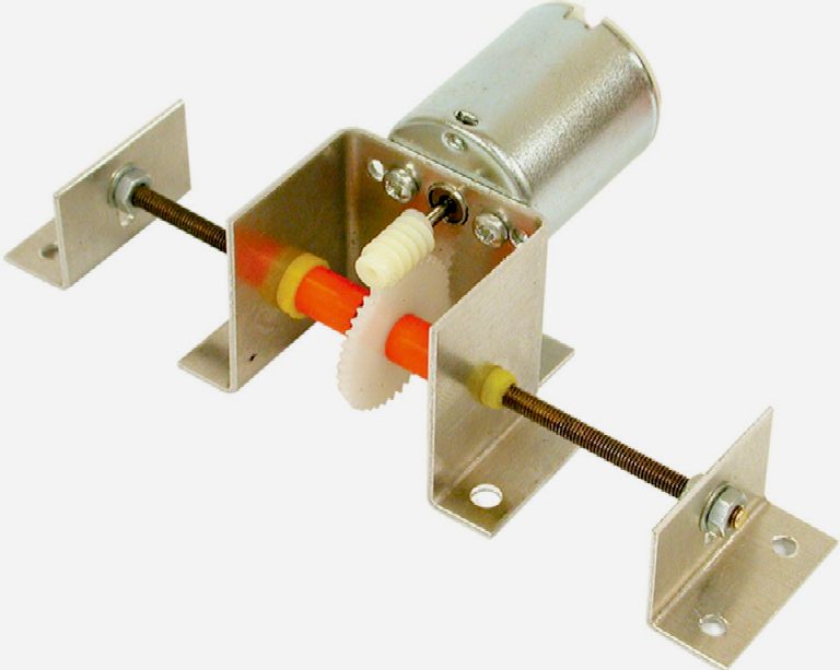
An example layout: The outrigger actuators may be either hydraulic or mechanically driven, the latter by a geared thread running in lubricated for life low friction screw blocks. Both systems may be manually overridden in emergencies. The advantage of the geared screw system is that when locked, it is as if the outriggers are not active - which despite the low drag advantages, some operators might prefer. This general setup could also be the basis for triple axis energy harvesting - components not shown here - and a further patent application.
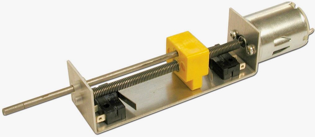
LINEAR ACTUATORS - These very simple motor driven screw threads work to amplify the torque of the driving motor to provide a linear push or pull. The left hand version uses a nylon worm gear to drive a nylon hub along a threaded shaft that remains bolted in place, to move a carriage assembly. The right hand version shows a motor directly driving a threaded shaft to move a block and pin, for a lot less shove, but a quicker movement. Aluminium brackets are used to keep the weight down. A similar setup could be used in the prototype active hull, with some refinements.
STABILITY
For our purposes, stability is just as important as reducing running drag.
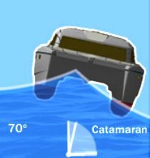
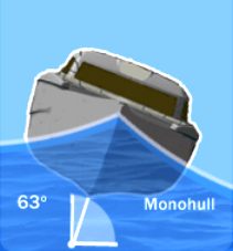
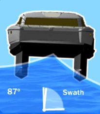
When considering vessels that are powered by energy from nature, it is just as important to keep the hull stable, as it is to reduce drag. This is because, at 63 degrees of roll in 6 feet waves, solar panels will lose a good deal of the incoming solar radiation - and that makes monohulls an unattractive proposition for a solar powered boat. A catamaran is much better at 70 degrees, but a SWATH or SWASH hull is the ultimate with just 13 degrees of roll for a tracking system to cope with. Bonza mate. One day we (someone) might achieve funding to do the basic research that is needed to prove the concept.
LIST and PITCH CONTROL MEDIUM
The next question is do we use mechanical devices to control pitch and yaw, or do we go digital? We are inclined to keep things simple (KISS) as you know, but there are many advantages to electronic control systems - especially if going the robotic autonomous route. For the feasibility stages of this project we will be using analogue switching.
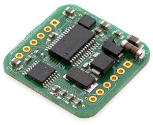
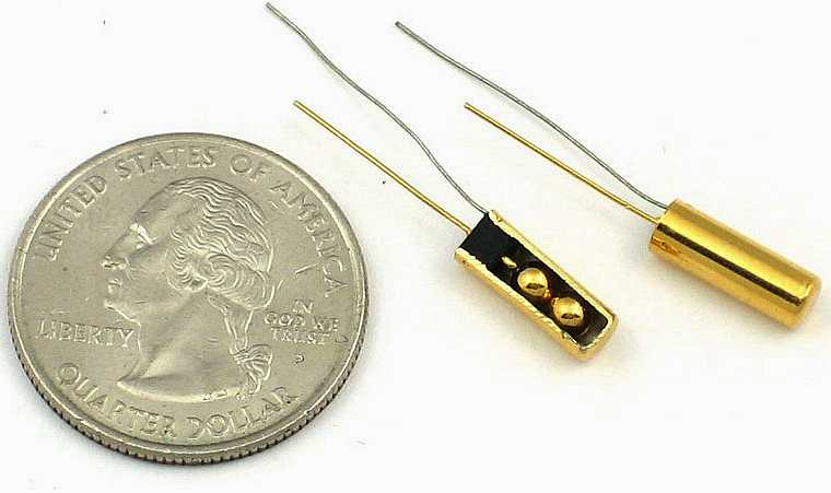
LEFT: The LCP-45 is a low cost dual axis inclinometer sensor supplied in a PCB format for mounting onto 0.1" PCB headers. It has a digital interface with a full duplex RS232 output as well as a TTL level (3.3V) UART for connection directly to a micro-controller serial port. A housed version with cable is also available at under £40. RIGHT: The SST162 inclinometer is high reliable tilt angle measurement product for mobile construction machinery industry applications, factory automation, solar equipment and transportation machinery. Either of these devices could be the basis of a low cost control system that would keep a Bluefish hull running true. Such a system would operate in parallel with other equally fundamental systems to control hull drag.
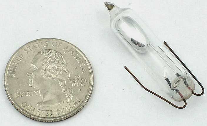
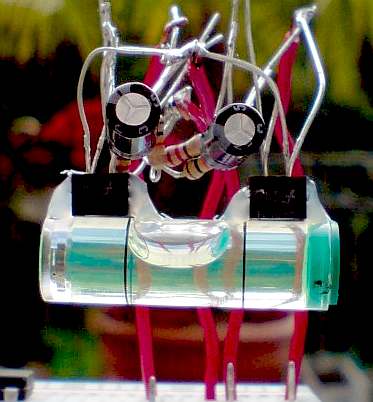
Now some really basic stuff. A mercury tilt switch; a rolling ball tilt switch and a board mounted version. Many vehicle alarms and the like are based on these items.
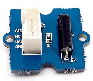
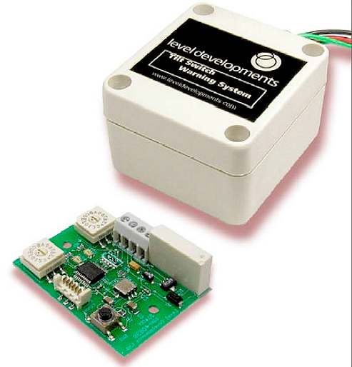
LEFT: Lets make robots home build of a proportional tilt switch based on light sensors and a spirit level. RIGHT: Electronic Tilt Switch module for high accuracy and low cost from Level Developments. The exact switching angle can be adjusted with the pcb mounted rotary switches. With the dual axis version the tilt threshold (the trip angle) can be adjusted individually for the X and Y axis. Once the tilt threshold is reached the relay operates and the switch contacts are closed. This can be used to sound an alarm, switch on a warning light, or interface directly to a machines control system, such as a boat list controller. The units incorporate analogue and digital filters to give a response suitable for vehicle tilt monitoring. The off-the-shelf components will save our engineer time, though he has recourse to a robotic designer who subcontracts to BMS, should he wish to develop a unit for a particular application where nothing suitable is available commercially.
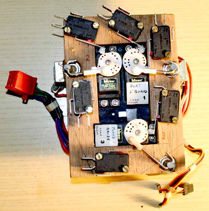
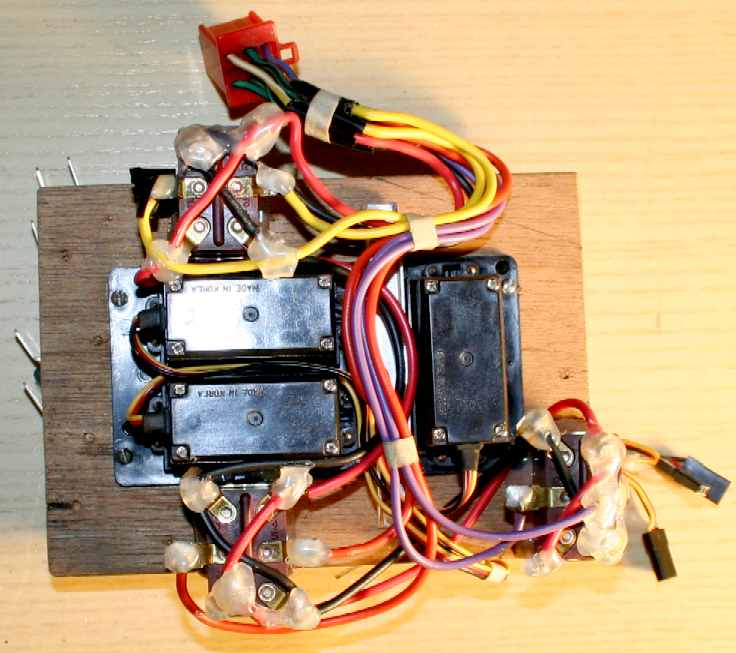
AUTONOMOUS CONTROL - R/C servos can be used imaginatively to perform complex tasks to stabilise a model ship, without the need for electronics. The simple triple servo pack shown above, with the rotational heads shaped into cams to form limit switches, linked to a third activation switch, was wired to tilt switches - to keep a model boat upright in the water - even where float height was a variable that an operator could control remotely from the shore via water pumps. This older system is a bit heavy for the Bluefish tank test model. A revised version would use micro-servos and switches to cut the mass in half.
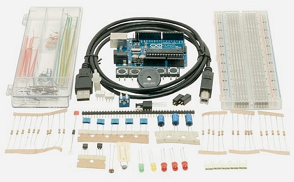
AUTONOMOUS CONTROL - The alternative to the above may be several hundred lines of code and one of the, now extremely popular, Arduino mini computers. These days most model makers like to include active devices. This is an ideal way of teaching young programmers how to achieve something real after all their hard work. This is a kit of parts to get you started on some quite challenging projects.
HOW THIS TRANSLATES INTO A FASTER SHIP
Having seen the basic tools for robotically controlling the ship's attitude, take a look at the pictures below as to use of the active outriggers to trim the vessel to obtain the optimum energy harvesting (from solar and wind) in combination with trimming of the hull(s) to keep drag from waves and wetted hull area to a minimum. The ideal is to have just the main submerged hull in the water for as much of a mission as possible.
ABOVE LEFT: The Bluebird™ yacht shown above has mid-range (partially) raised turbines in a high beam wind, the vector causing roll to port (the vessel is shown heading toward us). The autonomous trimming system compensates for this running condition using the active outriggers, by raising the starboard outrigger out of the sea and lowering the port into the sea. The main hull of the vessel then remains vertical, the deck horizontal. ABOVE RIGHT: A similar situation applies in this depiction, except that the wind is faster, as in a storm and coming from the port side. For this reason the turbine boom has been lowered to reduce roll, while the port outrigger has been raised out of the sea to take away buoyancy on that side, to effect vertical running. By this means the ship can trim itself to harvest as much energy from the wind as it is safe to do, while still maintaining the best running speed in any given weather situation.
DESIGN: The outrigger hulls must have sufficient reserve buoyancy to counteract the wind energy that will generate significant heeling moments, levered against the central submerged hull (to begin with), which acts as a fulcrum and centre of roll, transferred to the opposing outrigger progressively as the boom is raised higher, which then seeks to lever the main hull out of the water - as the opposing outrigger becomes the fulcrum. A ton of force against a lowered wind-turbine array (boom) will require a ton of buoyancy. A ton of force against a raised boom will require up to three three times that of the lowered boom - a mechanical disadvantage that all sailing ships have to contend with. In the case of a monohull, typically with a weighted keel, levered against the main hull's centre of roll. In the case of a multihull, by spacing the hulls wider apart to prevent capsize. This yacht design is capable of self-righting.
ABOVE LEFT & RIGHT: The same Bluebird™ yacht is shown here in a head on (or following) wind. Here the conditions are such that the active hulls must be in the sea to give a comfortable horizontal ride for any crew - or simply to maximize on energy harvesting - especially from the solar panel arrays. The design of this vessel is © August 2014 and the technology is patent applied for.
ABOVE LEFT: In this picture, conditions are such that the Bluebird™ yacht hull is balanced so well that it does not need to have either the port or starboard outriggers in the sea as stabilizers. This will reduce the running drag of the vessel to the absolute minimum (as a mono-hull) - unfortunately, not all of the time. We cannot explain here how this is achieved because of patent publication laws, that would otherwise prevent grant. ABOVE RIGHT: Compare the wetted surface area of all three hulls in the water, with the single hull on the left. The design of this vessel is © August 2014 and the technology is patent applied for.
CIRCUMNAVIGATION EXAMPLE - The above table illustrates one of the most likely ocean awareness expedition routes showing the time elapsed in days for 7 knots average cruising speed, including times for 5 and 6 knot averages - allowing for 10% downtime and 36 days in ports. Hence, although the objective is to reduce the current solar circumnavigation record from 584 days, the event in not an outright non-stop yacht competition in the offshore racing sense. It remains to be seen how accurate such a prediction might be.
BALLAST TANKS
A ballast tank is a compartment within a boat, ship or other floating structure that holds water.
Submarines don't have active hulls, as in moving sections, apart from control surfaces, but they do trim the attitude of the hull, using fore and aft trim tanks. The MK1 & 2 SWATH hulls that were tested in earlier developments, used a similar system in two hulls, giving four-point (fore-aft and port-starboard) trim capability. Interestingly, the Concorde supersonic passenger plane pumped fuel to adjust flight angle for landings and take off.
SADDLE
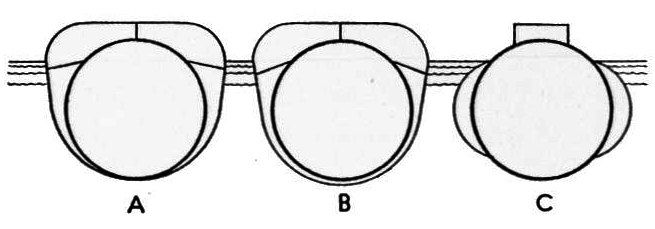
TANK DEVELOPMENT
Saddle, or pannier tank development evolution. A and B used a lot more metal with increased complexity. Cost and speed of manufacture is important during times of war.
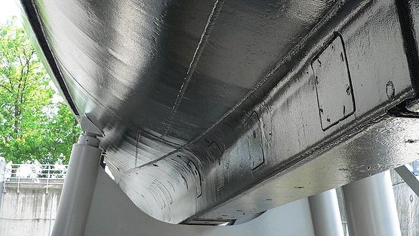
THE KINGSTON VALVE
A Kingston valve is a type of valve fitted in the bottom of a ship's fuel, water and ballast tanks. Named after its
inventor John Kingston (1786-1847), an
English engineer.
The Kingston Valve is clearly visible on the underside of this historic submarine.
The above describes certain ballast tanks, such as safety, negative and bow buoyancy tanks on vintage submarines. In general, main ballast tanks have the Kingston valve atop the tank. This Kingston valve, controllable both manually and hydraulically, is known by some as main vent operating gear. Main ballast tanks are in pairs; one on each side of the boat. One Kingston valve serves a pair, but each tank has a vent riser, with air connections and stop valves in the vent riser. The tank bottom is open to the sea through flood ports. The trapped air in the tank provides positive buoyancy while on the surface, although sea water sloshing in through the flood ports must be removed occasionally from the ballast tank(s) when cruising on the surface by means of low pressure air.
A ballast tank is capped by a vent riser, a pipe coming out of the top of the tank that terminates at a Kingston valve. In the vent riser is a valve that when shut, prevents flooding the tank when the submarine is rigged for surface. When the sub is rigged for dive, this valve is opened and flooding the tank becomes an option. Normally, the tank is flooded when the Kingston valve is opened, usually hydraulically from the control room. This Kingston valve then is left open until time to surface comes. This is because a slight leak of air from the air line provided to blow the tank into the vent riser could slowly make the boat more buoyant.
When surfacing, the Kingston valve gets shut so the introduced air gets trapped in the tank and pushes the water out the tank's bottom through the flood port. The Kingston valve associated with each ballast tank can be operated manually. The vent riser valves get opened or shut manually during the rig for surface or rig for dive procedure.
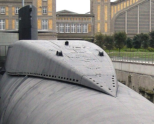
You can see the ballast tank vent hatches on the rear deck of this submarine.
SUBMARINE VENT
In submarine technology a vent is a valve fitted to the top of a submarine's ballast tanks to let air escape from the top of the ballast tank and be replaced by water entering through the opening(s) called "flood ports" or "floods" at the bottom of the tank. In earlier times, the openings at the bottom of the ballast tank were fitted with valves known as Kingston valves. These valves were eliminated in the
U.S. Navy between the World Wars.
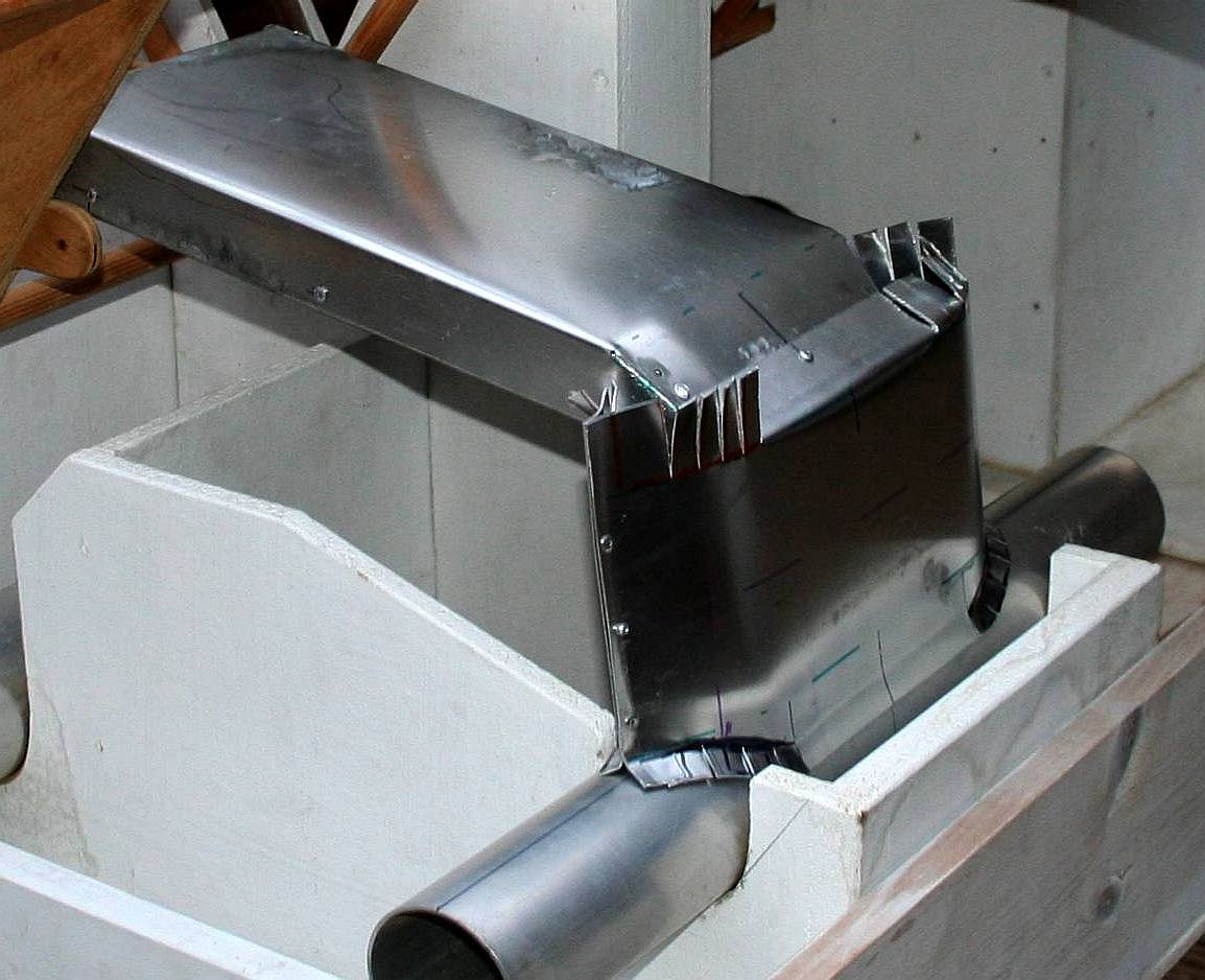
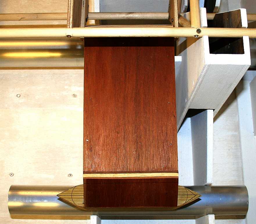
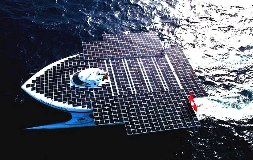
Photo of the Bluefish/SNAV development model, overhead view of the active outrigger hull all nice and square thanks to our jig. The objective of the active legs is to stabilise the vessel for minimum water and wind drag, whilst still retaining a good reserve buoyancy in case of storms and high angles of heel. This wooden outrigger was made on the 2nd of September at the same time as the Turanor PlanetSolar was visiting London. Photos taken and posted on the 3rd September 2013.
AN ACTIVE WEIGHT CHART - is more than simple figures, it steers development - early figures:
So far we are well within our target. Let's hope it stays that way as the last few gadgets are fitted. The weight of a ship always goes up during fitting out, never down.
OTHER ACTIVE (AUTOMATIC) TRIM SYSTEMS - HUMPHREE
Humphree is based in Gothenburg on the west coast of Sweden. The company is dedicated to providing “Speed at sea” through innovative technology solutions for high performance vessels. The company was founded in 2001 by a team of hydrodynamicists and marine engineers, active in the field of marine high-speed propulsion and ship hydrodynamics since the early 1990’s.
The
objectives of the company is to provide cutting edge products to increase
the potential of all types of fast vessels using a new kind of trimming
device to optimize a vessels running trim. The flagship system
incorporates Automatic List and Trim Control that corrects trim and also
the angle of list to a preset target angle, usually zero degrees. This can be
manually changed by the operator to intentionally list the boat.
The latest development is said to fine-tune just about every aspect of its systems’ performance, whether installed aboard yachts or ferries.
Especially impressive is the ATOS (Automatic Trim Optimisation System) function, which offers huge potential fuel savings – a 10-15 per cent reduction is claimed – on any planing or semi-planing hulls from as small as 13m (43ft) up to 100m (330ft) and more.
Humphree Interceptors – often referred to as ‘super tabs’ – replace traditional trim tabs and provide improved fuel consumption, cut CO2 and NOx emissions, increase speed and improve acceleration as well as onboard comfort. They can easily be adopted to fit any shape of hull, even those with propeller tunnels and waterjet installations. They are also useful for reducing waves and wash, which is important for vessels operating in ‘sensitive’ areas; wake or wave height can be reduced by 20 per cent or more.
These tabs will not work with submerged hulls, where fins or other active features would need to be employed as in the Bluefish system above - which must also run as close as possible to zero degrees of list.
DRAG THEORY
Uneven loading, cross winds and varying conditions will normally cause the boat to list.
Generally the resistance of a boat is made from the following components: Surface friction, Form resistance, Surface roughness, Wave resistance, Air resistance & Appendage drag. Obviously, these will also change with the speed of the boat.
In a planing or semi planing hull the wave resistance is around 50% of the total resistance. By changing the trim of the boat, the wave resistance can be significantly reduced.
The figures obviously depend on the size of a vessel. For example, by
comparison to its length an oil tanker will see wave drag evened out to
become insignificant seen against water friction. The graph below is a
rough guide to the general resistance components for different type of hulls.
A large vessel such as an oil tanker, would not benefit much from an active hull, save for triple axis energy production. Certainly, a submerged central form would offer no advantages. Conversely, in smaller vessels needing to remain list free at low energy levels, there is a huge potential performance increase.
HUMPHREE CONTACTS
REFERENCE LINKS
Trimaran neutral carbon Giles Vaton Soliloquy zero carbon superyacht Alistair Callendar Wikipedia Archimedes principle Solar Navigator Inventors archimedes Wikipedia Archimedes principle http://en.wikipedia.org/wiki/Ballast_tank http://en.wikipedia.org/wiki/Waterline http://en.wikipedia.org/wiki/Archimedes%27_principle http://www.solarnavigator.net/inventors/archimedes.htm http://en.wikipedia.org/wiki/Archimedes%27_principle http://en.wikipedia.org/wiki/Displacement_%28fluid%29 http://en.wikipedia.org/wiki/Displacement_%28ship%29 http://www.cyberiad.net/leo.htm
Solar House, BN27 1RF, United Kingdom + 44 (0) 1323 831727 +44 (0) 7842 607865
BLUEFISH DEVELOPMENT PROJECT INDEX A-Z
EARLY SOLAR BOAT LINKS
Blackcurrant 1 | Blackcurrant 2 | Catamaran Hull Design Drag | SWASH | SWATH | Trimaran
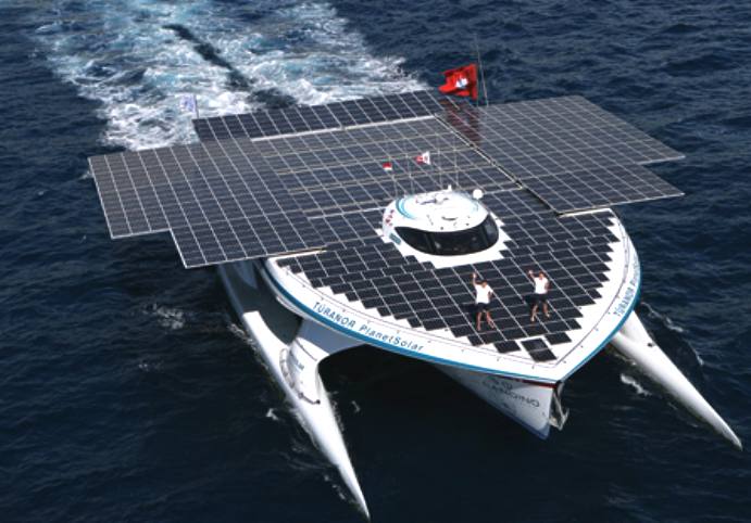
The biggest and fastest solar boat as of September 2013. The fastest Atlantic solar boat crossing took just 22 days to get from the Canary Islands to St. Martins in the Caribbean.
NOTE: The models seen on these pages are being constructed under license for testing of the robotic, solar and wind energy harvesting systems, - using radio control initially, switching to computer micro-controller for fully autonomous robotic control.
|
|||||||||||||||||||||||||||||||||||||||||||||||||||||||||||||||||||||||||||||||||||||||||||||||||||||||||||||||||||||||||||||||||||||||||||||||||||||||||||||||||||||||||||||||||||||||||||||||||||||||||||||||||||||||||||||||||||
|
This page is Copyright © 2017 Bluebird Marine Systems Ltd. The names Bluebird™, Bluefish™, SeaNet™, SeaWolf™ and the blue bird & fish in flight logos are trademarks.
|
|||||||||||||||||||||||||||||||||||||||||||||||||||||||||||||||||||||||||||||||||||||||||||||||||||||||||||||||||||||||||||||||||||||||||||||||||||||||||||||||||||||||||||||||||||||||||||||||||||||||||||||||||||||||||||||||||||