|
|
SWASH - SUBMERGED SINGLE HULL WITH ACTIVE STABILIZATION
|
||
|
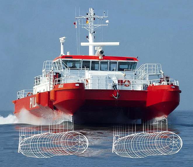
As a good example of a SWASH hull, the Explorer from Abeking & Rasmussen is an interesting concept. It uses a relatively large diameter single submerged hull with narrow fins and two thin, almost wing like section port and starboard outriggers, as the stabilizing element of the design. The outriggers are rigidly fixed to the main hull via the superstructure. The ship is relatively short.
CONVENTIONAL HULL THEORY
Most naval architects will know that less engine power is needed for tri-hull configurations at moderately high speeds (trimarans). This is mainly as a result of decreased wave-making resistance from the narrowness of the hulls - hence, there is a reduced frontal area and the angle of water deflection is slight. Catamarans also have an advantage over monohulls for similar reasons. Here we are speaking of surface vessels that are subject to wave making resistance.
Let us now consider going beneath the waves like a torpedo or submarine. These sub-surface vessels are not subject to wave making drag, provided that they stay below the surface at sufficient depth to escape turbulence. If we now apply the wisdom of reduced frontal area, as in multihull configuration, we should get some interesting results.
This is where SWATH and SWASH hull-forms potentially have an advantage. To date both SWATH and SWASH hulls have been short rigid structures with no active element. That is a great pity, because it is possible to trim a hull as one might trim the sails of a sailing ship, to improve performance. Even powerboats have trim tabs to correct attitude, so increase speed - and more speed of course equals a more efficient hull.
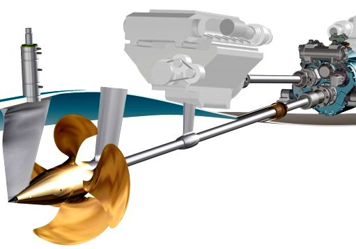
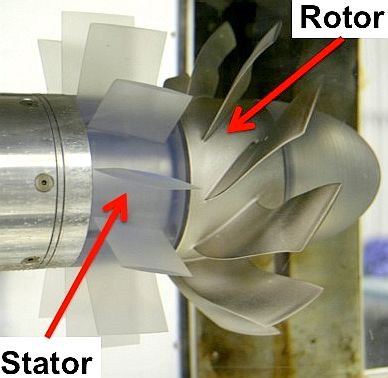
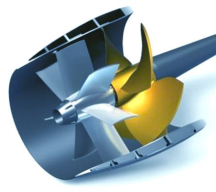
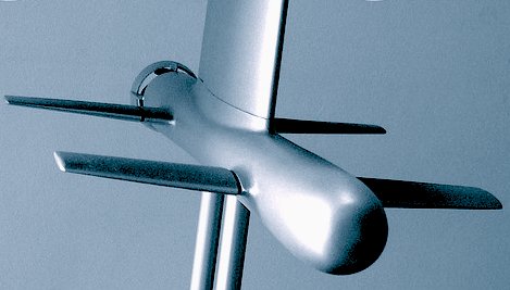
Evolution of the propeller, from inboard IC engine to propulsor via a prop-shaft, to a submerged pod containing an electric motor, to a propeller with a pre-swirl stator ahead of a propeller. The pre-swirl stator increases thrust efficiency by around 5%. Whatever propulsion system is used, the design of the vessel's hull is far more critical. But every little helps.
THINKING OUTSIDE THE BOX
In conventional thinking, naval architects assume that a boat hull is a blob in the water, which they must somehow power through the water. Pushing a boat or ship through the water in the age of engines invariably involves turning some form of propulsor, typically a propeller. The shape of the blob to be pushed was a brick with rounded ends, but the entry and exit of the brick through the waves has now become important, where previously the cost of making the hull was the primary consideration.
Today, the cost of fuelling the engine is important, with new anti-pollution laws focusing attention on efficiency. Fleet operators have realized that there are other options, such as multihulls, and that took us through catamarans and trimarans to SWATH and now SWATH hulls. The reason for this was the search for the minimum wetted area, because wetted area = drag, and drag equals more fuel.
CONVENTIONAL SWATH THEORY
Advantages for SWATHS are:
(1) the ability to deliver big-ship platform steadiness and ride quality in a smaller vessel and (2) the ability to sustain a high proportion of its normal cruising speed in rough head seas. The theory is to obtain the least possible wetted area, which is a submerged cylinder (a submarine), ignoring length for now. The total resistance of a catamaran twin-hull ship at moderately high speeds is roughly 50% frictional and 50% wave-making or form drag. That's a big 50% of wave making drag for smaller ships for us to look at. By submerging a hull to a reasonable depth, wave drag is all but eliminated - the ideal being a smooth laminar flow, troubled only by the foil shaped legs that join what is below the water, to the bits above that humans need to control the ship.
SWATH ships are usually much shorter than a monohull or conventional catamaran of equal displacement. This is partly to minimize the weight penalty caused by the more deeply submerged hulls that a SWATH vessel has. In addition, the smaller water-plane area makes it necessary to have wider hull spacing than used on conventional catamaran twin hulls, for the same lateral stability.
Conventional thinking here is that a shorter length minimizes the frictional resistance penalty from the submerged hulls, where otherwise the higher wetted area per foot of length, would detract from the overall design advantages. Another disadvantage is that twin-hull SWATH configurations often have relatively high wave-making resistance, due to their short speed length ratio and also increased displacement as a result of the greater structural mass inherent in the design.
The wetted area of each hull of a SWATH is 0.794 x 0.794 = 0.63 x that of the monohull. The displaced volume for each hull is 0.50 x that of the monohull. It follows that the wetted area per ton of buoyant volume for the SWATH hull is (0.63/0.50) = 1.26 x that for a geometrically similar monohull (geosim).
This means that SWATH ships have a 26% percent higher total frictional resistance than would a monohull small-waterplane-area ship of the same (geosim) displacement.
A pure submerged triple hull (one with three equally sized submerged hulls) would have an ever higher total frictional resistance if we apply the square-cube law. A quad submerged hull would be even worse, and so on.
For comparison purposes it is useful to think of the 2 hulls of a SWATH ship as geosims* of a single-hull small waterplane area ship having twice as much displaced volume, or buoyancy. I.e. the same volume in one round hull, as split into two round hulls.
Each dimension of a geosim, such as hull length, is related to the corresponding dimension of a single submerged reference hull by, the linear scale ratio, which is defined as the cube root of the ratio of their displacements. Thus, the length of each SWATH ship hull is (0.500)^0.333 = 0.794 x the length of a monohull small-waterplane-area ship of twice the displacement.
We should not get carried away by the above, where other factors such as form have a bearing on drag. It is not simply wetted area.
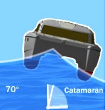
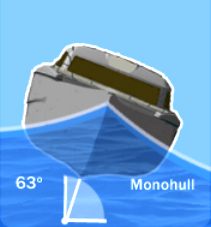
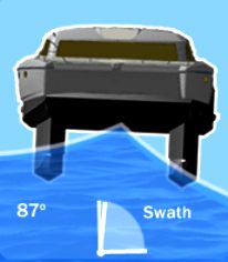
When considering vessels that are powered by energy from nature, it is just as important to keep the hull stable, as it is to reduce drag. This is because, at 63 degrees of roll in 6 feet waves, solar panels will lose a good deal of the incoming solar radiation - and that makes monohulls an unattractive proposition for a solar powered boat. A catamaran is much better at 70 degrees, but a SWATH or SWASH hull is the ultimate with just 13 degrees of roll for a tracking system to cope with. Bonza mate.
SWATH HISTORY
- 1938 to 1994
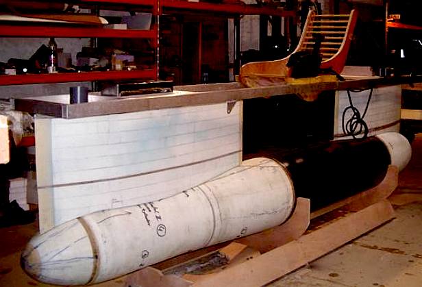
Abeking & Rasmussen constructed this 5 meter development boat as part of their SWASH ship research and development programme. A simple box section frame is used to attach the two outrigger pods. Check out the wooden deck chair style seat for the test skipper.
1970 - Mitsui Engineering & Shipbuilding Co., in Tokyo, begins basic research on the "semi-submerged catamaran", or SSC.
CONVENTIONAL SWASH THEORY
For a triple hull, the wetted area per ton would be 1.44 x that for the monohull with three times larger displacement. In such an example, total (pipe) frictional resistance would rise to 144 percent that of the monohull and about 114.5% more than for a comparable conventional twin-hull SWATH ship. Thus a triple hulled vessel like this is a no, no.
However, if one uses a large central submerged small waterplane hull to carry the loads of the vessel, for say 90% of the total displaced volume, then use two stabilizing outriggers, in trimaran layout as seen in the top diagram, to account for the remaining 10% of buoyancy, the total frictional resistance disadvantage falls to 105% of a comparable conventional SWATH vessel. By contrast, the wave-making resistance falls dramatically, hence there would be a substantial overall decrease in total resistance if it were not for the foil area adding up to a total drag increase. For this reason, early drag performance results showed that more horsepower was needed to propel both SWATH and SWASH hulls, over a monohull. Whereas, less power is needed for surface running catamarans and trimarans.
Tests conducted by the Naval Ship Research Centre, Maryland in 1974 (model 5301) gave disappointing results, mainly due to hull configuration and the inability to trim for horizontal running. In these tests the hull was running bows up and the central support foil was nearly full length, a formula bound to increase running drag significantly. SWATH ships also have this bows up attitude, leading to increased drag. The conclusion must be that some means of correcting attitude and trimming for the least running drag is needed to realize the potential of the SWASH concept. For some reason, the US Navy did not see fit to develop the concept further, despite the shortcomings of the tests.
ZCC SWASH THEORY
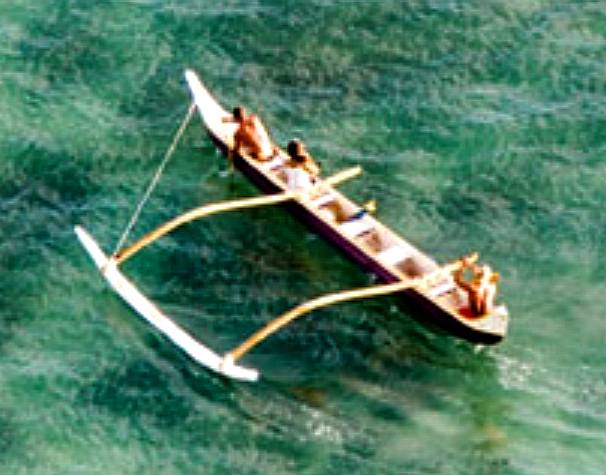
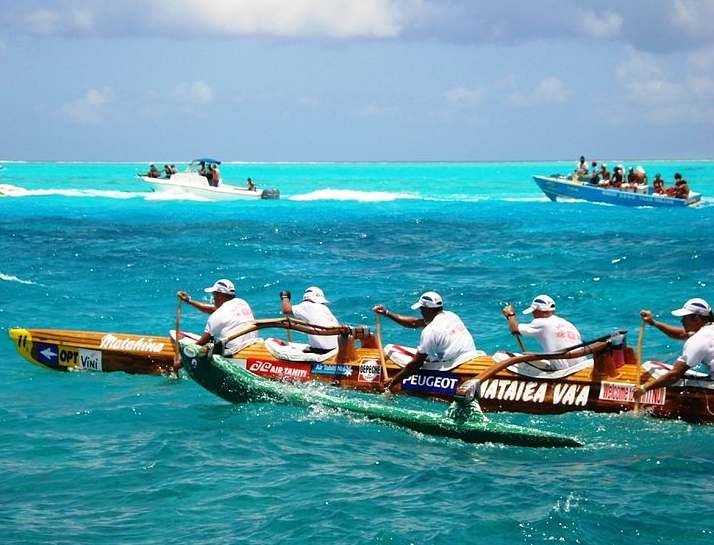
The first thing to consider is changing the general configuration, by which means the drag may be reduced considerably. We can take this a stage further with an active hull, because we can trim the vessel, such that only 5% (or less) of any combination of outrigger is needed to stabilize the vessel - virtually achieving monohull status in certain conditions. The Polynesians discovered this and perfected the art with their canoes. Outriggers though, still have to ride the waves, so there is room for improvement. The way forward is not as with model 5301, and we cannot tell you here about the most current designs, where these are the subject of research and development due to begin in late 2014, or early 2015, depending on funding becoming available. So fingers crossed......
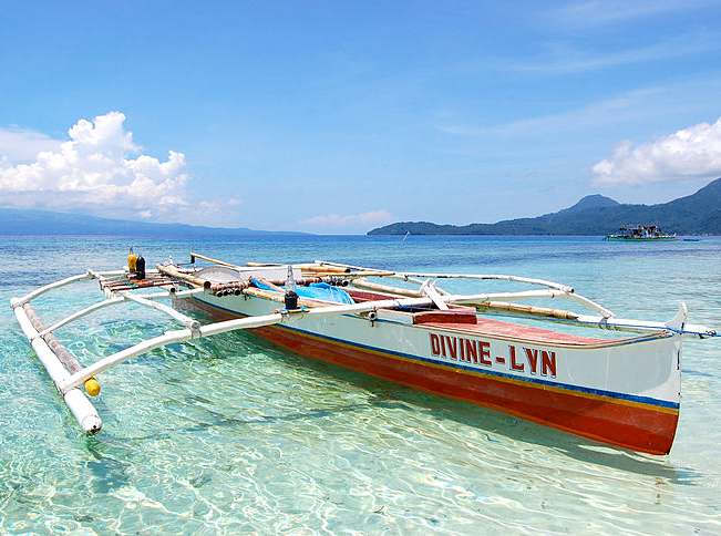
The earliest Polynesian navigators figured out that it was much easier to paddle a long and thin canoe, and that it could be made stable by simply attaching a float on the end of a two poles. Simples. It was so easy to paddle one of their outriggers, that even the ladies got a kick out of it. Oxford and Cambridge, eat your heart out.
OTHER ACTIVE HULL ADVANTAGES
Why stop there? Now that we have created an extremely stable fulcrum and from that starting point, we might use wave energy to propel the hull, or at least to contribute to propulsion. It is possible therefore to take advantage of waves that would otherwise slow us down by impacting outriggers, etc, to speed us up. Whoa. Naval architects will have a fit if we suggest that conventional wisdom should be thrown out of the window, but that is what we are doing. More on this after we have conducted the planned series of theoretical experiments by way of initial research, to see how best to take advantage of this concept. I feel a thesis coming on......
To conclude, conventional theory would rule out SWASH hulls. It is only by testing new ideas that progress may be made. Sometimes you have to go against the trend and think outside of the box to get ahead.
The concept design of this HYSWAS craft is based upon an existing hull design which has been developed by several companies, such as the Maritime Applied Physics Corporation in America, as prototyped by their technology demonstrator - ‘The Quest’ - in 1995. An auto-pilot ‘fly-by-light’ system from the aviation industry could take control of difficult roll forces and maintain ‘foil borne’ speed - also controlling pitch and heave. This hull form has two working ‘waterlines’ for its operation. At low speed the Tetrahedron sits gently onto three underbelly hulls. At high-speed the hydrofoils rotate on the submerged hull, raising the triangular superstructure out of the water.
HYSWAS
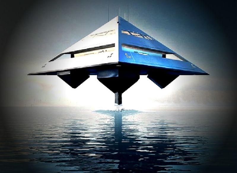
TRINITY - Tetrahedron Motor Yacht - Flying Triangle
The superstructure form is reduced geometrically to that of a simple tetrahedron. A three-based pyramid consisting of 4 faces and 6 leading edges provides fundamental stability and enclosure. Its form produces a pure, precise and mathematical ‘roof’ for which to connect to the hull assembly. Simple forms are not common in ship and motor yacht construction through restrictions in ocean-going hull design. Schwinge designs seek to address this issue, taking convention to its logical conclusion.
The Tetrahedron would have the appearance at high-speed of ‘levitating’ over the water: a boat that can fly. This is produced by a HYSWAS hull - A Hydrofoil Small Waterplane Area Ship - that is comprised of a single retractable vertical strut onto a single submerged ‘torpedo’ hull. The vessel will lift out of the water at speed on side-mounted adjustable hydrofoils.
It is claimed that long distances are possible with reduced out-of-water drag, that during stormy ocean conditions would incur virtually no slamming. Improved efficiency is driven by elevated hydrofoil propulsion and would be one of the key performance benefits of this type of design.
SWINGE CONTACTS
Schwinge Limited
Tel: +44 (0) 20 7403 6298 Website: http://www.schwinge.co.uk
LINKS & REFERENCE
SOLAS'1974 www.maritimejournal.com/ship-and-boatbuilding/a-and-r-makes-waves-with-new-swash-design http://www.motorship.com/news101/ships-and-shipyards/mono-swath-from-abeking-and-rasmussen http://en.wikipedia.org/wiki/International_Convention_for_the_Safety_of_Life_at_Sea Types of Automatic Identification Systems". U.S. Coast Guard Navigation Center. Maritime Navigation and Radiocommunication Equipment and Systems IEC. Tron AIS-SART - AIS-SART / Radar SART JOTRON. http://www.cmlmicro.com/Press/briefs/index.asp?/Press/briefs/ais.htm Circular 289: Guidance On the Use of AIS Application-Specific Messages Establishing an IALA AIS Binary Message Register: Recommended Process IALA Conference AIS Application Specific Messags IALA-AISM. http://www.maritimejournal.com/ship-and-boatbuilding/specialist-german-yard-makes-swath-history http://www.maritimejournal.com/ship-and-boatbuilding/first-swath-patrol-boat-for-latvian-navy http://articles.maritimepropulsion.com/From-SWATH-to-SWASH-Further-development-at-AbekingRasmussen
NOTE: An important factor affecting performance is the ratio of hull wetted area to displaced volume. This ratio follows the scale 'square-cube law' - Wetted area is proportional to (scale ratio)2 - displaced volume is proportional to (scale ratio)3.
|
|||
|
This website is Copyright © 2014 Bluebird Marine Systems Limited. The names Bluebird, Bluefish and the blue bird and blue fish in flight logos are trademarks.
|
|||