|
|
SCOUT TRANSATLANTIC HULL DESIGN
|
|
||||||||||||||||||||||||
|
Scout's hull is a classic displacement design with relatively fine entry and exit (canoe form) in ideal calm water conditions. She also has wing flare extensions rising to a raised deck - creating instability, which is resolved by weight placement in an elongated keel.
Scout is therefore subject to conventional 'speed-length-ratio', or Froude calculations - but with complications arising from additional drag from wash spray drag, due to its small scale in relation to open ocean size waves.
Basically, any very small displacement vessel will have serious performance limitations from the environment - because, by design, it is not well suited to surpass nature, where waves are large - if that is, efficient transport is the case in point. In this case it is not. The objective is to prove autonomous navigation is possible. While efficiency has been a consideration, hull innovation is not the main objective. In the circumstances, Scout's hull compromise is commendable.
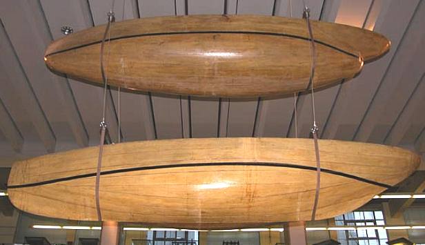
The wooden Swan and Raven experimental model boat hulls of William Froude, seen in the Science Museum in London. All the postulation in the world in nothing compared to physical testing and proof of concept.
THEORY LWL = HULL SPEED
Hull speed, or displacement speed, can be thought of the speed at which the wavelength of a boat's bow wave is equal to the boat length. This is applicable to surface vessels in displacement mode.
As boat speed increases, the size of the bow wave increases, and therefore so does its wavelength. When hull speed is reached, a boat in pure displacement mode will appear trapped in a trough behind its very large bow wave, from which traditional designs cannot escape.
Generally,
increasing the length of a displacement hull will increase its economic speed.
One was of escaping this rule is to lift a hull out of the water so it planes
across the waves. But this is not possible under a certain power to weight
ratio. A solar powered boat will not have sufficient power to achieve planing
speeds.
As a ship moves in the water, it creates standing waves that oppose its movement. This effect increases dramatically in full-formed hulls at a Froude number of about 0.35, which corresponds to a speed-length ratio (see below for definition) of slightly less than 1.20 (this is due to a rapid increase of resistance due to the transverse wave train). When the Froude Number grows to ~0.40 (speed-length ratio about 1.35), the wave-making resistance increases further due the divergent wave train. This trend of increase in wave-making resistance continues up to a Froude Number of about 0.45 (speed-length ratio about 1.50) and does not reach its maximum until a Froude number of about 0.50 (speed-length ratio about 1.70).
SPEED LENGTH RATIO = HULL SPEED
Hull speed can be calculated by the following formula:
where:
The constant may be given as 1.34 to 1.51 knot·ft −½ in imperial units (depending on the source), or 4.50 to 5.07 km·h−1·m-½ in metric units.
HULL FORM
Wave making resistance depends dramatically on the general proportions and shape of the hull: modern displacement designs that can easily exceed their 'hull speed' without planing include hulls with very fine ends, long hulls with relatively narrow beam and
wave-piercing designs. These benefits are commonly realised by some canoes, competitive rowing boats, catamarans, fast ferries and other commercial, fishing and
military vessels based on such concepts.
FROUDE NUMBER
The Froude number (Fr) is a dimensionless number defined as the ratio of a characteristic velocity to a gravitational wave velocity. It may equivalently be defined as the ratio of a body's inertia to gravitational forces. In fluid mechanics, the Froude number is used to determine the resistance of a partially submerged object moving through water, and permits the comparison of objects of different sizes. Named after William Froude, the Froude number is based on the speed–length ratio as defined by him.
where v is a characteristic velocity, and c is a characteristic water wave propagation velocity. The Froude number is thus analogous to the Mach number. The greater the Froude number, the greater the resistance.
ORIGINS
In open channel flows, Bélanger (1828) introduced first the ratio of the flow velocity to the square root of the gravity acceleration times the flow depth. When the ratio was less than unity, the flow behaved like a fluvial motion (i.e., subcritical flow), and like a torrential flow motion when the ratio was greater than unity.
SHIP HYDRODYNAMICS
For a ship, the Froude number is defined as:
FROUDE APPLICATIONS
Blackcurrant 1 | Blackcurrant 2 | Catamaran Hull Design Drag | SWASH | SWATH | Trimaran
DRAG
In fluid dynamics, drag (sometimes called air resistance or fluid resistance) refers to forces which act on a solid object in the direction of the relative fluid flow velocity. Unlike other resistive forces, such as dry friction, which is nearly independent of velocity, drag forces depend on velocity.
Drag forces always decrease fluid velocity relative to the solid object in the fluid's path.
Types of drag are generally divided into the following categories:-
Wave drag occurs when a
hull is moving through a freely-moving fluid surface with surface waves radiating from the
hull.
where
where D is some characteristic diameter or linear dimension and ν is the kinematic viscosity of the fluid (equal to the viscosity μ divided by the density). At low Reynolds number, the drag coefficient is asymptotically proportional to the inverse of the Reynolds number, which means that the drag is proportional to the speed. At high Reynolds number, the drag coefficient is more or less constant. The graph to the right shows how the drag coefficient varies with Reynolds number for the case of a sphere.
POWER
Note that the power needed to push an object through a fluid increases as the cube of the velocity. A car cruising on a highway at 50 mph (80 km/h) may require only 10 horsepower (7.5 kW) to overcome air drag, but that same car at 100 mph (160 km/h) requires 80 hp (60 kW). With a doubling of speed the drag (force) quadruples per the formula. Exerting four times the force over a fixed distance produces four times as much work. At twice the speed the work (resulting in displacement over a fixed distance) is done twice as fast. Since power is the rate of doing work, four times the work done in half the time requires eight times the power. It's important to value the rolling resistance in relation to the drag force.
BOUNDARY LAYER
& AIR LUBRICATION
One way of reducing a vessels skin friction (and to some extent form) drag, is to introduce air bubbles at bounding surface, so reducing viscosity.
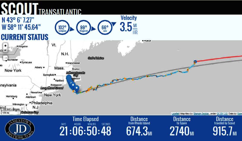
14 SEPTEMBER 2013 STATS Time Elapsed:
21 DAYS: 06 HOURS: 50 MINUTES: 17 SECONDS
Visit the Scout website at www.GoTransat.com
AUTONOMOUS NEWS UPDATE 2021
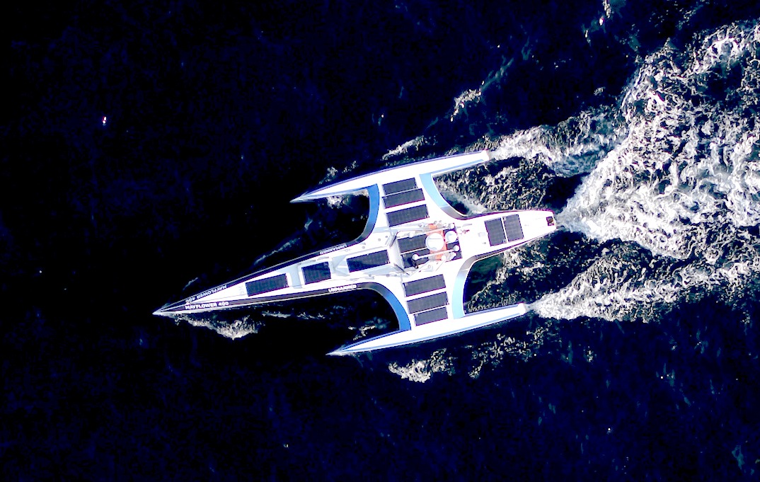
Following on from the Scout Atlantic bash in 2013, in 2020, a team comprising Promare, IBM, and many other technology partners, decided to attempt to cross the Atlantic against the prevailing winds and currents. They set out to build a 100ft craft named Mayflower Autonomous Ship (MAS) for launch and an attempt, aiming for the 400th anniversary of the Pilgrim Fathers journey starting on the 6th of September 1620.
They never made that date, partly due to Covid 19, but did manage to get a hull in the water for the ceremonies in Plymouth, Devon in 2020. On the 15th June 2021, the unmanned craft departed from Plymouth in England, aiming for Plymouth, Massachusetts, USA. You can follow the journey on their blog: https://mas400.com/dashboard
MAS 400 - The fully autonomous trimaran Setting off from Plymouth, England on the 15th June 2021. There are solar panels, that presumably add to the diesel-electric setup. The idea is to be COLREGs compliant with a self learning program, as such vessels build a database. Much the same as with the current bevy of self-driving robotaxis and robotracks. The question is therefore, will ships beat trucks to the autonomous punch?
LINKS
http://en.wikipedia.org/wiki/Boundary_layer http://en.wikipedia.org/wiki/Ship_resistance_and_propulsion http://en.wikipedia.org/wiki/Wake http://www.bluetraker.com/solutions/fuel-monitoring/ https://twitter.com/ScoutTRANSAT https://www.facebook.com/ScoutTransatlantic http://www.wpri.com/on-air/green-team/ri-students-design-solar-powered-boat http://www.solarracing.org/2013/06/10/autonomous-solar-powered-boat-to-cross-the-atlantic/ http://letsmakerobots.com/node/38270 http://www.kickstarter.com/projects/601285608/scout-the-autonomous-transatlantic-boat http://www.kickstarter.com/help/school#defining_your_project http://www.kickstarter.com/start?ref=footer http://www.gotransat.com/ http://www.gotransat.com/tracking/ http://makezine.com/magazine/transatlantic-drone-takes-to-the-sea/ http://www.behance.net/gallery/SCOUT-Transatlantic/10153015 World
Sea
conditions, Temperatures
& Sunshine http://www.yellowbrick-tracking.com/ http://fishpi.org/wiki/index.php?title=The_Proof-Of-Concept_Vehicle http://fishpi.org/wiki/index.php?title=The_Prototype http://fishpi.org/wiki/index.php?title=Hull_Design http://www.raspberrypi.org/ http://international.findmespot.com/ http://www.amsat.org/
|
||||||||||||||||||||||||||
|
This website is Copyright © 2013 Bluebird Marine Systems Ltd. The names Bluebird™, Bluefish™, Solar Navigator™,Blueplanet Ecostar BE3™, Utopia Tristar™ and the blue bird and fish in flight logos are trademarks. The color blue is an essential element of the marks. All other trademarks are hereby acknowledged.
|
||||||||||||||||||||||||||