|
|
SNOOPY SLOOP ROBOT BOAT
|
|
||
|
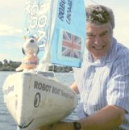
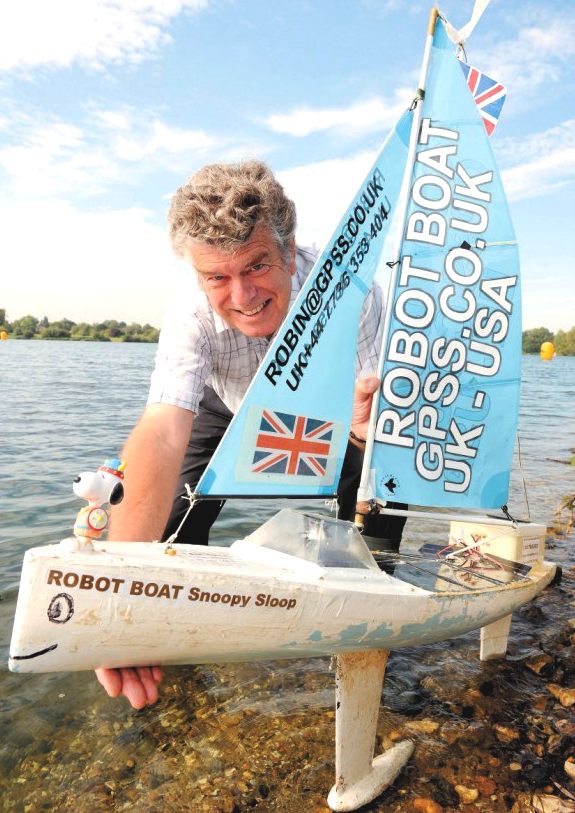
Robin Lovelock at the helm of Snoopy Sloop
Oh boy. It's hard enough to get out of any tidal area, let alone with steering issues.
LATEST LAUNCH OCTOBER 2013
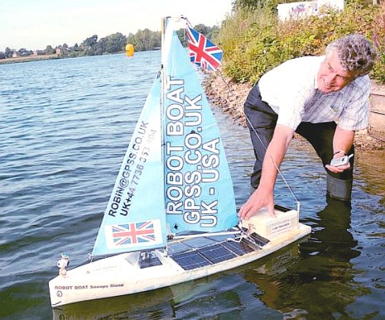
Snoopy was launched at 1215pm on Friday 11th October in
flat calm sea conditions, as it was predicted on MagicSeaweed. Thus the team did not have to suffer the problems experienced in March, of "getting past the surf". Conditions looked perfect, including a stiff offshore breeze approaching 20mph.
Marvelous!
Robin Lovelock gets wet as he says farewell briefly to his robotic chum: Snoopy Sloop
The American team is not having much more luck with their solar powered Scout, but they did set a new distance record for autonomous vessels of over a 1,000 miles, before Scout decided to go walkabout. The launch seems to be one of the hardest parts for all of the challengers, be they wind or solar powered. Snoopy is much smaller that Scout. Where size matters in the big bad ocean, this is a disadvantage. But it remains to seen how much of a problem that might be once Snoopy gets through the English Channel. We will of course do a featured report on that, the day it happens.
LEGAL STUFF
In common with all of the entrants to Microtransat, Snoopy Sloop has no collision avoidance system, thus is not COLREGs compliant, but it comes into a category (a gray-area) that to all intents exempts small craft. Whereas, our (BMS LTD) main concern for a larger vessel is recognition for the safety of unmanned craft - as a necessary progression. One might argue that the challenge is daunting enough without this additional complication.
Vessels must show due consideration for The Safety of Lives At Sea. Small autonomous craft will have low kinetic energy. Recent experiments would indicate that the bow wave of large vessels pushes small vessels out of the way and the possibility of an impact is small. Impact against a model boat of this size is also unlikely to damage a sea going vessel - and that may be all the 'regard' that is required for the Microtransat. Hence these vessels may not 'be in command' during the race but - this is considered acceptable - except perhaps for the competitors where total loss is an issues for those who value their craft.
A tracker should be installed, these projects relaying the boats position hourly and automatically displaying the position on a website. This would be available to the commanders of sea going vessels should they wish to consider avoiding the yacht.
THE CHALLENGE
Choosing to send a small robot boat across the Atlantic is a difficult task. At this scale the boats are battling what amounts to hurricane winds (full size), most of the time. Thus stability is the first issue to be resolved - not something that comes easy to a sail powered boat with loose rigging. The other main challenge is the launch, when onshore breezes invariably work against the vessel, which comes back to shore surfing style - a regular feature of the launch attempts.
Possibly, the weakness in design in the case of the sailing boat, Snoopy Sloop, is not the autonomous navigation electronics, but the marine environment, which is unforgiving. Most vessels that operate successfully in the oceans, are solar/electric or wave/sail powered. These seem to work, or at least the tracking systems work well enough that recovery crews stand a chance.
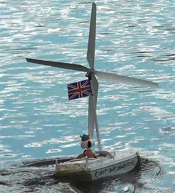
The windmill Snoopy boat is another lesson in design dynamics, and a bit of a wind-up for aficionados. This boat was launched as a bit of fun and the fact it kind of worked shows that with development, rotary sails have potential. In this case the center of buoyancy is too high. It's easy for us to say this, we know, but dear reader, we have every admiration for Robin and his (serious) efforts with Snoopy Sloop. Our comments are therefore meant in a friendly way, and we are simply joining in the Banta.
Snoopy Sloop - Top heavy rotary windsailer. Click on Snoopy to see more about rotary wind sailing boats. They can work rather well and need much development, which will be by amateur yacht designers, but only because at the moment there is no money in it.
ABOUT THE DESIGNER
Robin Lovelock graduated in 1969 with a B.Sc in Electronics Engineering. He specialized in real time computer systems and as a student had been particularly interested in artificial intelligence and pattern recognition. He was influenced by HAL, the speaking computer in Kubrick's film '2001 a Space Oddesy', in turn inspired by Arthur C Clark. The defence contractor Ferranti sponsored his progress through university.
Robin worked for ten years as a NATO scientist, followed by 14 years of management within the UK Defence Industry in the command and control business. From about 1991 Robin got into PCs and GPS software. At this time he started in business in his spare time. In 1994 Robin left EASAMS (the Systems House of GEC-Marconi) to start "Sunninghill Systems" (GPSS) full time.
ABOUT
GPSS
The main source of income for Sunninghill Systems has been provision of high-value configurations of GPSS to those that need them, an example of which is for use for Inmarsat-C communications, where the licence per computer was 10,000 pounds. Sunninghill Systems upgrade the GPSS product for customers who need it to do something extra to meet their requirement. e.g. process messages received in a different format. These improvements to the product may remain 'hidden' (as for the Inmarsat-C logic), or become available to all. The cost of upgrades are negotiable, depending upon the effort required to implement the change, and the likely increased value of the upgraded GPSS product.
WHAT THE DAILY MAIL SAID
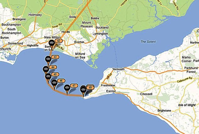
A retired scientist spent four years building a toy boat he hoped would be the first to cross the Atlantic unaided - only to see it crash after six miles. Robin Lovelock, 65, waded into the sea in his trousers to launch Snoopy Sloop from Barton-on-Sea, Hants, on a 3,600-mile journey to the U.S. But the four-foot vessel sailed just six miles in seven hours before crashing into the Needles off the western tip of the Isle of Wight.
The 30lb boat, which has a top speed of just three knots, was constructed for less than £450 in Mr Lovelock's games room in Sunninghill, Berkshire. It features solar panels on the deck that power a GPS receiver, a small computer, and a turbo, which control the metre-high sails and rudder. Mr Lovelock tracked the journey on the internet from a laptop after his boat set sail at 11.30am, but watched in horror as winds carried the boat straight into the rocks. He then lost contact with Snoopy Sloop at 6.45pm after the motion of the waves repeatedly bashed it against the rocks, breaking the onboard GPS.
The former senior scientist for NATO now hopes a member of the public will be able to rescue the boat so he can try again. He said: 'It was always going to be tough so I am not too downhearted.
'Hopefully somebody will find Snoopy and return her to us so we can give her a quick dusting down and send her back on her way. 'She made good progress for the first two hours but then we noticed she was heading straight for the Needles, where she is wrecked. 'The repeated bashing against the rocks has unfortunately broken the GPS receiver. It’s possible water has got on board.'
He added: 'If we had launched her just a few hundred yards further west or half an hour earlier she would have probably missed the Needles and be well on her way now.' If the boat had survived the six-month journey to Maine, it would have been the first robotic boat to complete the transatlantic trip.
The technology should have worked to keep the 10kg boat on a a pre-defined route, mapped out by Mr Lovelock. He started work on his project four years ago, assisted by six friends called the Last of the Summer Wine Team, one of whom appeared on BBC programme Robot Wars.
The boat has previously already sailed 5,000 miles, albeit in the comparatively still waters of Bray Lake near Windsor.
He said before the launch: 'It will be a tough trip with lots of obstacles to trip us up along the way.
It was due to head west along the English Channel from the Hampshire coastline, south towards the Azores to catch the trade winds, then to the Bahamas and on to the USA.
A team from Aberystwyth University attempted the first transatlantic crossing in September 2010 setting sail from Valentia, County Kerry, Ireland. But the team lost its track of the craft off the north west coast of Ireland.
Snoopy's first attempt on the Atlantic in November 2012. Maybe you can help in discovering who "snatched" Snoopy, or where Snoopy went after his time near that military bunker ? Before that you will see the pictures and videos of Snoopy's more recent short-lived attempts, in his new boat, in March 2013.
Some readers will be more interested in the boat, others in the control system. We at Bluebird Marine Systems are interested in both, but there is nothing innovative about the boat hull, nor the energy harnessing sails. That is of course our opinion based on observation. On the other hand, the navigation system is much more interesting, because so many teams are trying different hard and software combinations - failing yes, but that is the fun of the competition. Experiments rarely succeed straight away.
SNOOPY's AUTONOMOUS NAVIGATION SYSTEM
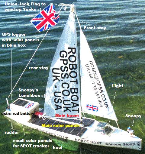
1. the GPS Logger sub-system, including solar panel.
Robin included a GPS Logger to comply with the Microtrasat 2012 rules.
The GPS Logger in Snoopy Sloop is an off the shelf 'I-GotU Travel Tracker' from Maplins, costing approximately £45 complete with USB cable (for charging internal battery). The +5v and 0v (USB) pins were connected to a small 6v solar panel firstlt mounted on the lid of it's blue plastic box. The solar panel is 6v 100mA 100x55m, mounted so as not to shade GPS in the I-GotU - and so that the red power/charge light is visible. A blue flashing light shows the logger is working. The software with the I-GotU was used to log a GPS position every 12 minutes, cyclicly. It holds 65,000 waypoints, so this holds the last 1.48 years (nearly 18 months) of GPS tracking.
2. the "Navigation" Light sub-system, including solar panels.
A solar powered light was added to comply with the Microtrasat 2012 rules. As per the rules the light switches on automatically at dusk, gives a 360 degree continuous white light, and switches off automatically at dawn.
It is based on the LEDs, electronics and solar panel from a ordinary garden solar light, this one chosen for having brighter LEDs than many others.
The two AA unbranded batteries were discarded and replaced by two higher capacity 2000mAH NiMH cells. The original enclosure was discarded and an assembly, with an additional four solar panels around the side, was built into an upside-down pyramid shaped plastic pudding bowl. Transparent silicon sealant was used to join the assembly to the bottom cut out of plastic. The additional solar panels, were 4v 80mA 65x65mm connected via blocking diodes to the battery. Transparent silicon sealant was used to fix the light to the front deck. This was subject to the 24/7 testing on Bray Lake, as part of the total boat system.
3. SPOT Tracker sub-system, including solar panels.
In his Mk1 version, Robin used a very crude means of making the SPOT Messenger send regular position reports every hour using a PICAXE based timer to operate a servo to press the "OK" button on the SPOT to initiate a position report. A neater version of this SPOT tracker system, was put in a boat for 24/7 tests on Bray Lake - until the SPOT Messenger failed - after months of continuous operation. The Mk2 version does not need a servo.
The SPOT tracker needs to run for the duration of the Atlantic crossing - maybe for as much as a year! Robin decided to make changes to the tracker, such as an extra set of batteries linked to a small solar panel so that the system SHOULD remain working indefinitely.
With
the SPOT switched ON, it drew about 2mA - due to flashing the "on" LED; when the
[OK] button is pressed it draws about 80mA for the 15 minute SPOT transmission cycle.
That told Robin the approximate power needed from batteries and solar panels, as
in 80mA for 15 mins - 20mA average draw. If only
one transmission per day the draw is nearer to 3mA. But once an hour was chosen to ensure
the team got regular position updates.
Two small solar panels, nominally 6v and 80mA output, in parallel, seemed enough to keep the batteries topped up for months of typically English dull weather. At risk of "blowing something up", the second (external) battery pack was added, consisting of three Ni-MH (Nickel Metal Hydride) cells, giving a nominal 3 x 1.2 = 3.6v. The Ni-Zn and Ni-MH packs were charged separately and "balanced" before connecting together, including the solar panels. Robin is a brave man. We'd have used identical batteries. But the complex system worked.
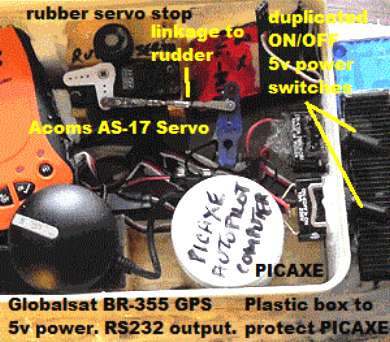
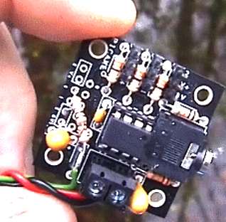
Both Mk1 and Mk2 of our SPOT tracker used the same type of PICAXE Servo Driver board as used for the autopilot. The three wires from the PICAXE Servo controller, that normally go to a servo, are connected directly into the SPOT Messenger. The red and black power leads connect to the 3.5v SPOT power. The voltage is normally sufficient to operate the PICAXE SPOT Timer. The third (white) wire is soldered into one of the SPOT Messenger [OK] switch contacts via a 10k resistor.
The Timer software program, inside the PICAXE, has a 60 minute delay, then operates the [OK] button, to start a position report transmission, then resets for another 60 minute delay. The count to achieve the hour pause is accurate to about 1 second per day. This took some calibration tests for that particular PICAXE board, where the PICAXE speed varies with component temperature and power supply voltage. The team experiences some difficulty before getting it right.
4. the Autopilot sub-system, including GPS, PICAXE, and Rudder Servo.
To
begin with the team's autopilot was based on an iPAQ Pocket PC, running Microsoft Windows Mobile and Robin's GPS Software for Pocket PC called GPSSppc.
These early autopilots were based on the computer controlling a vane-rudder,
which in May of 2011 saw Snoopy Sloop 5 completing the Bray Lake Test, sailing
nicely between waypoints.
The PICAXE consumed far less power (1mA) than an iPAQ, and it showed promise of being a simpler, more reliable, computer.
With sleeves rolled up again, boat number 6 was built for first tests of the PICAXE autopilot,
in time for their first sea test.
During the 24/7 tests the team did find one flaw (or "feature"?) of the servo: if the 5v power dropped very low (below 3v) due to prolonged days without sun, there was a tendency for it to "creep" clockwise. If this went too far, the servo linkage risked "flipping over", reversing the rudder movement. When power restores, such as at dawn, the PICAXE restarts, but if reversal has occurred the rudder will not steer as intended. The solution was to introduce a rubber stop, to limit how far the servo can creep. Under normal use, and normal power input, the servo cannot reach the stop. This 'bodge' was used because it would take too many months of repeated testing with a different servo to reach the same level of confidence in it.
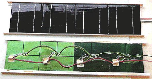
Snoopy's 5v power system for the autopilot consists of three NiMH batteries, in parallel, charged from the array of 8 x 6v solar panels, each 13cm x 13cm. The solar panels are sub-assemblies, supported by light weight L section plastic strips. The solar panels are connected in parallel with their own blocking diodes. The rear surface of the panel (including the copper printed circuit) is protected by layers of FastGlass Resin, varnish and then silicon sealant; also used to fix the assemblies to the deck.
The total average power consumed by the autopilot is less than 50mA, with the majority drawn by the GPS (~35mA), very little by the PICAXE (~1mA), and a small amount by the servo as 7mA drain with spikes of maybe 100mA when it moves. These are the figures with the loudspeaker and wind vane sensors removed - saving about 30%.
Early in their 24/7 testing on Bray Lake in April 2012, Robin used a single 2600 mAH 4xAA NiMH pack (as sold for use with radio control receivers). This small capacity was to test the total boat system in conditions where the power drops from it's nominal 5v (typically 5.2v), to as low as 3v, when parts like the PICAXE, GPS, and/or servo, will stop working. 2600mAH/50mA = approx 52 hours, meaning they occasionally got a low power condition during tests. When the sun came up, the system would normally restart and be running again within two or three hours of dawn. Thus, they knew the system would cope with power failure. This was also when they discovered the "servo creep" problem.
Snoopy Sloop completed most of it's 24/7 testing and was launched on it's Microtransat 2012 attempt with three battery packs in parallel: two 2600mA flat packs of AA cells inside the box, under the spot tracker, and a larger, red, 4 cell sub-C 5100mA pack immediately in front of the lunchbox. This gave a total capacity of about 10,300mAH or 10.3AH. The red, external pack was 4 cells, broken out of a 7 cell 8.4v pack from Hobby-Power.
The four 10AH D-sized cells are a neater way of providing a large capacity 5v battery. These "Extreme" 10000mAH (10AH) packs were a good buy on e-bay at £20. When soldering wires onto the cells, you will need a soldering iron that is beefy enough to cope with heating a large surface. It is better to have more heat to solder quickly, than to use a low power iron that gradually heats up everything. The 4-cell pack was protected by varnish and sealant before putting low into the hull. A similar approach was used for the SPOT tracker 3.6v battery, made from three D-sized 10AH cells, to be charged by two, smaller 5v solar panels, mounted either side of the lunchbox.
The purpose of the power switch on Snoopy-Sloop is for convenience when testing. The autopilot can be switched OFF, to stop movement of the rudder, when transporting by car, to or from anywhere. It may also be useful, for a quick test that the system is all working: switching OFF then ON will result in the autopilot software doing a startup test, moving the rudder left-centre-right-centre.
Each team has to write their own software, on a PICAXE or on some other computer, but they could start with testing their boat with our GPSSppc based autopilot, if they do not expect too high a level of support. Many will consider the Pocket PC to be obsolete - so maybe better to use something with more computing power.
The logic is intended to work if power is lost at sea and the system has to reboot from cold.
The Autopilot logic may be described as:
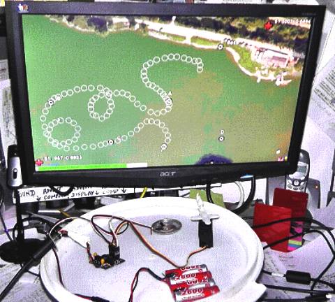
This picture shows use of Robin's "GPS Simulator" on his PC, to test the PICAXE autopilot software, particularly on it's planned route to the USA.
This
function is only used for testing locally in England on Bray Lake; it will not go to sea.
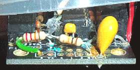
Ship-to-shore transmitter for Bray Lake testing: The picture on the left shows the completed transmitter box, that on the right shows the component parts used for in construction.
This is not relevant to the existing design, but is expected to be used for the next boat. In 2008 Robin was thinking of a flux gate compass to sense where the boat is pointing for the autopilot steering.
Their
simple GPS solutions use, instead, the direction the boat is moving - which is not
quite the same thing. Things like the tide can "confuse" the autopilot. Snoopy
Sloop can live with this design limitation if launched at the right time and place, to avoid the tide taking the boat onto the rocks.
However, if the team wanted to perform a sailing mission such as "sail around the Isle of Wight" -
they would need to have an autopilot that would handle the tide better, perhaps
to include an electronic compass.
Robin would like to thank Jim on the PICAXE Forum Robot Boat Thread, where he found the HMC6352 Compass Module which might do the job. More detail on that Thread. Thanks also to Thierry, for suggesting an alternative and his MAG3110 thread describing the software.
LIST OF COMPONENTS & SUPPLIERS - tips on where to get your bits:
Google and Ebay for many things, including model boat hulls, servos, GlobalSat BR-355 GPS with RS232 DIN plug, and SPOT trackers.
SPOT satellite communication air time and web services for SPOT map, at £90/100euro per year from www.findmespot.com
www.picaxe.co.uk for PICAXE computer - the AXE024 servo driver kit and faster PICAXE-08M2 chip.
www.firststopsolar.co.uk for our low voltage solar panels.
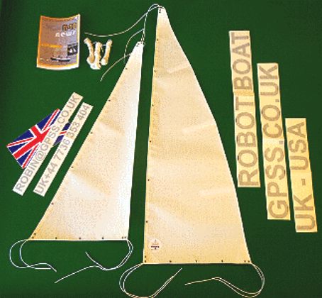
Sticky vinyl letters for sails. e.g. 34 2.5" high letters for 11 GBP. www.humberston-signs.co.uk
FASTGLAS RESIN and ISOPON P40 for water-proofing and strengthening - from Halfords.
"High Voltage 1.6V Ni-Zn 2500 mWh ...BPI" AA size cells from Maplins. Note 2500/1.6= ~1500mAH. With special Ni-Zi charger.
Larger 4xSubc 5100mA Ni-MH pack (from Hobby-Power, 7 cell pack) as used for model power.
"Extreme 10000mAH" Ni-MH 10AH cells via ebay.
Duplicated 4 cell packs based on Dyna-fun 3300mA, GP 3700mAH, and Panasonic 2400mAH AA cells. Diodes used to isolate.
"International Perfection" 2 part polyurethane paint (snow white colour) from local boat chandlery.
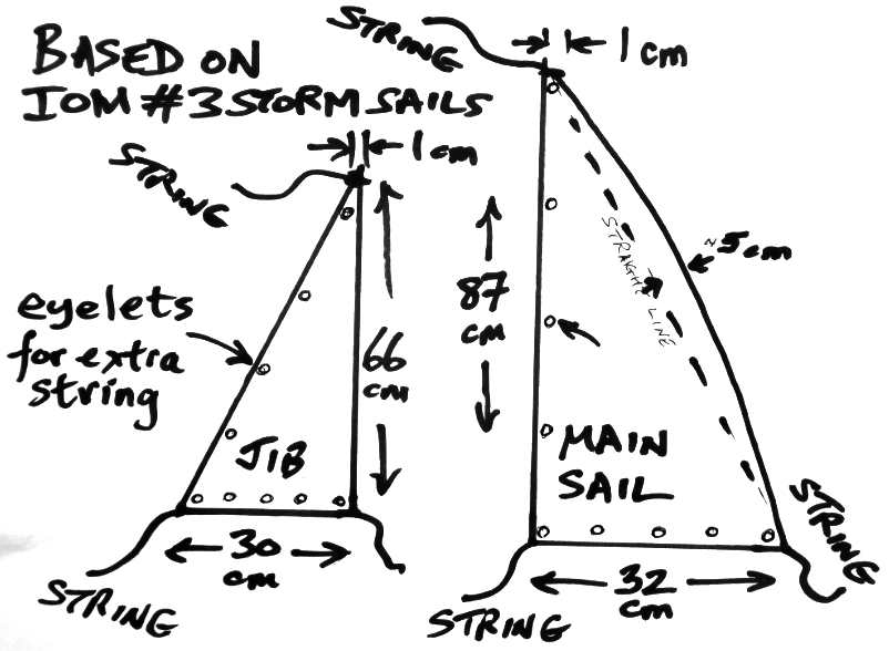
www.housemartinsails.co.uk for sails on boats 4,5,6,7 and 8 used in 2012: small IOM #3 storm sails, strengthened with sticky vinyl sheet.
www.nylet.co.uk for the much stronger IOM #3 storm sails for boat 9, built for Microtransat 2013. Braided Polyester cord (natural) from English Braids Ltd via Nylet: Sized 2.0mm and 2.2mm for boat 9 cordage ("strings").
PICAXE products, including Picaxe 08 servo driver: www.picaxe.com
USA source of Ametes 360AMSC-01 is GMW Associates: www.gmw.com
Alternative
direction sensor: AS5040
from Austria Microsystems,
SNOOPY's HULL
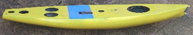
1. The "lunchbox" waterproof plastic enclosure for electronics.
As you can see from the pictures on this page, the new "lunch" box could be a larger across the hull for more freedom inside, but it cannot be much smaller. The rudder post comes up into the box from the rudder, so it can be driven by the servo.
The
first lunchbox was part of a wedding present given from 1971: part in a large picnic
hamper. Robin considered constructing a box himself, but this box was ideal because of
the airtight lid design. One problem is that no glue works that well, leaving
tape and silicone - a bit messy - but quick and effective.
a
a
a
CONTACTS
Sunninghill Systems,
Email: robin@gpss.co.uk Tel:
+44 1344 620775 - 0800 and 2030 UK time, business calls only.
Snoopy Sloop Youtube video diary
LINKS
The Design of Snoopy Sloop 2012 boat built for the 2013 race The Blog of tests and repairs Robin's hobby robot boat page: www.gpss.co.uk/autop.htm The Microtransat Challenge: www.microtransat.org www.bracknellnews.co.uk/2012/12/07/-rescue-mission-for-model-boat-on-transatlantic-voyage The
Microtransat Challenge for competition details Windmill
Boat video SPOT
Track from the Mail
Online World
Sea
conditions, Temperatures
& Sunshine
The
original Press
Release Family
video of Snoopy's launch The
underwater TV recce/winch boat used in 2009 "Rescue
of Snoopy" Video
of Snoopy Sloop for 2013 Jasper
Coppings article in the Sunday Telegraph http://www.yellowbrick-tracking.com/ http://fishpi.org/wiki/index.php?title=The_Proof-Of-Concept_Vehicle http://fishpi.org/wiki/index.php?title=The_Prototype http://fishpi.org/wiki/index.php?title=Hull_Design www.dailymail.co.uk/Robin-Lovelocks-boat-Snoopy-Snoop-crashes-just-SIX-miles-start-journey-Atlantic http://www.team-joker.com/ http://www.modelsbydesign.co.uk/ http://www.raspberrypi.org/ http://international.findmespot.com/ http://www.amsat.org/
If s picture is worth a thousand words, this must be the face that launched a thousand ships - well, half a dozen at least.
Learn about the (very) basics of model boat design using the links below - and why not have a go yourself.
Blackcurrant 1 | Blackcurrant 2 | Catamaran | Hull Design | Drag | SWASH | SWATH | Trimaran
|
||||
|
This website is Copyright © 2013 Bluebird Marine Systems Limited. The names Bluebird™, Bluefish™, Solar Navigator™,Blueplanet Ecostar BE3™, Utopia Tristar™ and the blue bird and fish in flight logos are trademarks. All other trademarks are hereby acknowledged.
|
||||