|
DINOBOT - GIANT ROBOT ANT - MECHANICS OF WALKING
ANTICS - ARDUINO - ARMOUR - ARTWORK - BIOLOGY - BLACK BOX - COMPUTERS - ELECTRONICS - ENERGY - FRAME FORMICARIUM - HEAD - JAWS - JIMMY WATSON - KITS - LEGS - MECHANICS - MOTORS - MOVIE - PHOTOGRAPHY - RASPBERRY Pi R/C DRONE - SENTRY SOFTWARE - SOUND PROOFING - SPACE ROVERS - SPEED - SUSPENSION - TAIL - UKRAINE DRONES - WEAPONS - WARGAMING
|
||||||||||||||||||||||||||||||||||||||||||||||||||||||||||||||||||||||||||||||||||||||||||||||||||||||||||||||||||||||
|
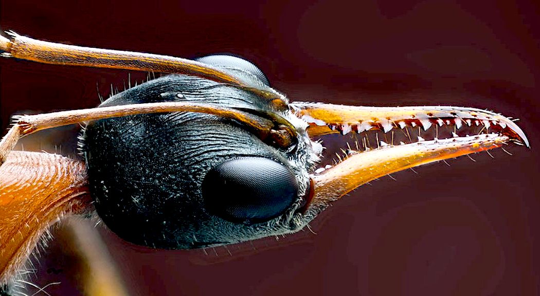
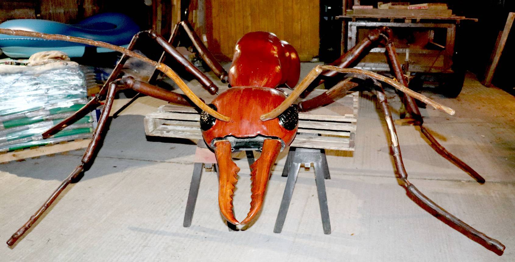
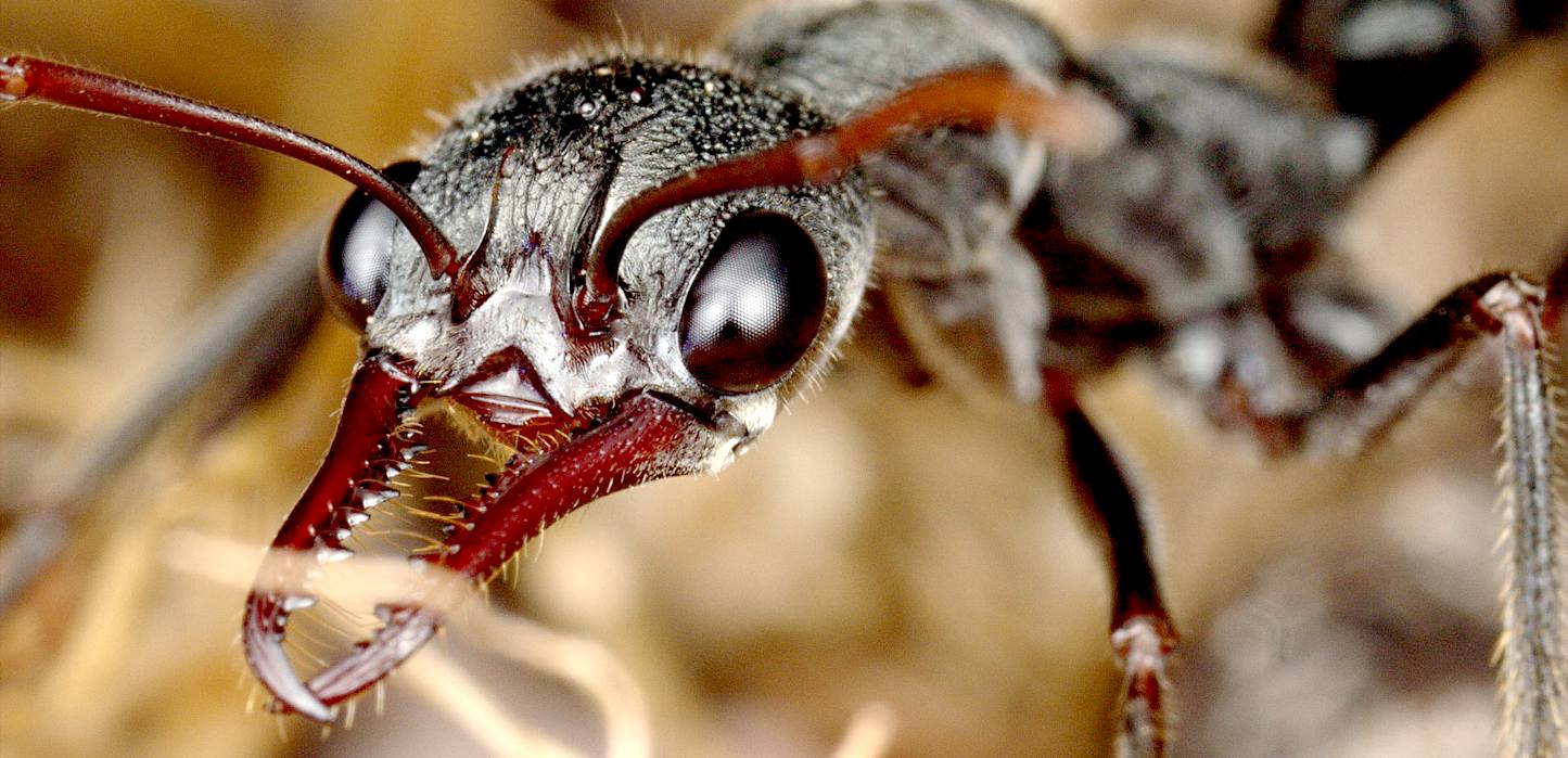
FABULOUS - You can't beat nature. We'll not be aiming to replicate this 100%, but doing an interpretation based on likely evolution with a lot of artistic licence thrown in.
CHRISTMAS GIANT ROBOT ANT PROJECT (DINO THE DINOBOT) - THE ABILITY TO WALK
Locomotion is essential for the most advanced life-forms on earth. Walking or running allows an animal to use planet earth more effectively to gather information or hunt food and find a mate. At the moment the only way to sustain life is to biologically procreate and that coupled with the need to constantly feed for energy, are the two main ingredients for intelligent life. These are the basic programs that all those engineers trying to simulate Artificial Intelligence seem to be missing. Intelligence is pointless without a purpose. Or looked at another way, intelligence makes a purpose more achievable.
Sometimes it is fun to just sit and watch an ant as it goes about its business, looking for food. It is constantly encountering obstacles, rugged terrain, leaves, sticks, and pebbles in its way. But it appears to navigate over or around all of these obstacles in an effortless way. It looks so simple, but it is really complex. The ant must have a number of Central Pattern Generators (CPG's) working for each leg, and each of them must be synchronized to work together in a rhythmic gait. If they did not, then the ant could try and raise 4 or 5 of its legs all at the same time and it would fall or squat. Or it could try and move all of the legs forward at the same time, and so on. But getting everything synchronized correctly so that the legs all work with the unified objective of propelling the ant forward or backward is much more difficult.
A NOTE ABOUT CONCEPTUAL DESIGN
Most people see obstacles to a complex machine working - and so never attempt a build. An 'inventor,' or 'conceptual design engineer' looks at problems the other way around. The premise is that something is possible until it is proven not to work. The starting point is to have a mental picture of all the parts that will make an idea come to life. That requires a good understanding of mechanics and materials as the starting point. Someone with no idea how to make things from different materials could not conceive how to combine those elements to achieve an outcome, because they lack the building blocks.
Equally, even if there is the engineering know how, these days that needs to be combined with electronics and finally, where robots are concerned; computers. Mental agility comes from experience combined with the willingness to experiment, where something has not been done before - and that requires confidence that a problem can be solved.
DINO
Dino the DinoBot uses insect-inspired locomotion control for gait generation, rough terrain mobility, and fault tolerance. We hope to demonstrate that Dino offers robust, flexible, real-time locomotion over a variety of terrain using some very basic sensors to make real-time course adjustments to avoid potentially damaging objects in its path - or even stop - if an object is insurmountable, reverse and seek an alternative route.
We are also looking at a simple version of the hydrolastic suspension that was developed for road cars in the 1970s to interlink the six legs in such a way that when one leg encounters a big rock and is forced up, the other legs are forced down to mitigate the height difference to some extent. If we use such a system it will not involve electronics, it will be either pneumatic or hydraulic based. But it must be economical and worth the extra design effort to bother with incorporation on production models.
INSECT LOCOMOTION - The above diagram shows a timeline that displays the tripod and metachronal wave gaits. The metachronal wave gait is the slowest of the gates for an insect. It is seen when a "wave" of leg movements ripples down each side of the insect. A good example of this type of gait is a caterpillar.
The tripod gait is the fastest of the gaits. In it, the insect always has two legs on the ground on one side and one leg on the ground on the other side such that it forms a tripod. So that three of the legs are on the ground and moving backwards while the other three legs are raised and moving forward. As the feet on the ground are moved back, this causes the body of the insect to move forward. Then when the raised legs are all the way forward they lower to make contact, and the legs that were down are raised and the whole pattern is repeated.
ALTERNATIVE TRIPOD GAITS - Several tripod gait sequences are possible. Two of the most obvious are shown above: IN RED - 1, 4, 5, 2, 3, 6. IN YELLOW - 1, 2, 4, 3, 6, 5. Please note that with revised numbering of the leg stations the YELLOW sequence could be: 1, 2, 3, 4, 5, 6. It all depends on how you choose to number your axles. An axle is one pair of opposing legs. So: front pair, middle pair and back legs. It remains to be seen which, if any, of the above sequences yields the fastest/smoothest walking speed and gait. That is half the fun of experimenting. You have to be prepared to have a go and be prepared for less than satisfactory results in the quest for perfection.
WALKING v RUNNING
Walking is easy. You can buy a $10 toy robot that walks in some kind of fashion. But, running at speed is another matter. Especially if you are 2.4 metres long and weight between 60 - 200 kilograms. Then telemetry might be worth a look-see as a means to improve performance.
If we built a robot on wheels we'd get better range because rolling resistance from the bearings and tires is really all we have to worry about - until a hill of course. This is though an artificial example, because wheels used in transport, such as for cars, run on prepared surfaces known as roads. Try taking a bike across a ploughed field and the man running on his own two legs wins the day.
Insects have six legs to worry about. In our robot, we don't want to waste energy lifting and lowering the chassis. We want the chassis to travel straight, with the legs evening out the ride - and for this we need a superior suspension. The suspension has to be geared to the optimum rotational speed of the legs. Our transmission is very basic, meaning that we need to refine the movement so that it is balanced. Any imbalance will mean efficiency losses.
A more complicated transmission with individual control of the legs fits onto the same chassis, but is really only for control obsessives and for doing tricks. We can increase the ability to cope with obstacles by adding a pneumatic muscle to raise rough terrain compliance to over a meter (3.25 feet). There is thus considerable scope for fine tuning and performance enhancement.
The fastest insect in the world is the Australian tiger beetles (Coleoptera: Cicindelidae). They can run @ 2.5 meters per second (5.6 miles per hour).
To convert the tiger beetles relative speed into human terms, a 6-foot man would move about 1026 feet per second or approximately 1/5 of a mile per second or 720 mph. That is not far off the ultimate land speed record of 763mph (1,227 km/h) held by Thrust SSC. Insect geometry can thus achieve high velocities if correctly designed.
INSECT LOCOMOTION - Some commonly observed gaits of insects. All are of the family of wave gaits.
Wilson (1966) presented a descriptive model for characterizing all of the commonly observed gaits of insects. Some of these gaits are shown in the figure above. These rules are adequate for describing the qualitative features of leg coordination in most insects when they walk on smooth horizontal surfaces.
There are common rules in relation to the above: 1. A wave of protractions runs from posterior to anterior. No leg protracts until one behind is placed in a supporting position. 2. Contralateral legs of the same segment alternate in phase. 3. Protraction time is constant. 4. Frequency varies (retraction time decreases as frequency increases). 5. The intervals between steps of the hind leg and middle leg and between middle leg and foreleg are constant, while the interval between the foreleg hind leg steps varies inversely with frequency.
Take a second and just think about how complex a task like walking really is. Most people simply take it for granted because it seems so effortless for humans, animals, and insects to just move their legs to go anywhere they want over rough, uneven landscapes. But if one really looks at locomotion, it is readily seen that it is not a trivial task. It takes a great deal of coordination between the different muscle groups to fire in just the right order, at just the right time to synchronize the leg movements. If the legs are not synchronized to work with each other, then the animal will fall down or simply thrash around. Uneven terrain also presents a formidable challenge in that the animal has to adapt its locomotion on the fly. If an insect is walking along and a rock is in its way, and it steps normally like it always does, then it may cause some of the other legs to no longer be touching the ground. This could mean that it would have trouble taking the next step and stumble, or could even fall over in extreme cases, when it picks up its legs on the other side for the next step.
STATIC STABILITY
CENTRAL PATTERN GENERATORS
VARIABLE TRACK STEERING
Variable track steering (VTS) is easy for a $10 toy robot. It is also easy for a human, a dog and a spider. But, when high-speed stability is needed for a machine with variable track steering, then the rules change.
All animals steer by varying the length of stroke of a leg movement (bipedal) or several legs is sequence, if you have four or more legs. Note that there are no animals with just one leg, three, five or seven legs. in other words, legs are always operated in pairs - mostly for balance.
Tracked vehicles use Variable Track steering to turn corners. This includes tanks and caterpillar type tractors and earth diggers or movers. Tracked vehicles are supposed to be able to grip well in slippery or unstable soil conditions, where wheels would stand no chance of gaining traction. Small tracked vehicles do not cope with rough terrain well. Apes cope with just about any terrain you can imagine, including climbing trees, but they are not that fast over flat ground. A Cheetah can run incredibly fast over grassland when chasing a zebra, but cannot swing through trees like an ape. A human can run on roads and climb trees, but neither of these functions as well as other animals - but then humans are the most adaptable species on and off the planet.
Our robot ant also uses a form of variable track steering. We must though ensure, that when we have turned a corner, reversed, or whatever, that the robot remains in sequence for high speed operation. How do we do that? All will be revealed in good time.
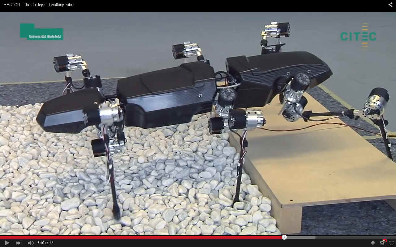
HECTOR
- The Biomechatronics research group of Bielefeld University, led by Prof. Dr. Axel Schneider, developed this six-legged walking robot using a stick insect as a model. For the design, the insect's measurements were increased by a factor of about 20. The total length of the robot is roughly 90 cm
and weighs 12kg. They say it's a giant stick insect, but it looks more
like an ant or a beetle. The project's goal was to better understand the gait of
insects and make the underlying coordination principles usable for technical systems. The research team also
wanted to investigate fundamental concepts for controlling elastically actuated robotic systems.
Now this is something we are also looking at.
DARPA'S BigDog from Boston Dynamics, is a quadruped that can run at 4mph (6km/h). It is powered by a 15hp 2-stoke go kart engine and has cost $millions to develop.
ANTICS - SITTING & JUMPING
In order to mimic some of the natural movements of an ant, we will have to modify the standard VTS transmission so that we have more control over each limb. Fortunately, this is possible without resorting to hydraulics or with the need to radically depart from the transmission that we need for ordinary locomotion. There are some seriously complicated motor/drive arrangements to try to achieve the movement we are looking for, such as 'Hector', from Bielefeld University in Germany, seen above.
We hope to achieve a similar level of adjustment to rough ground, without using much in the way of computing power, and more in the way of mechanical design adaptation. The object is to keep the transmission as simple, hence, as rugged as possible.
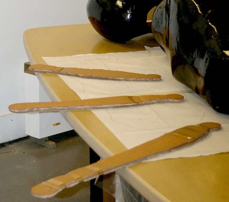
LEG MASS v COST - Aluminium legs in 28.5mm tubing is likely to be around £35 + delivery, whereas, titanium in 25 and 19mm tubing will run to £138 + delivery. The price for carbon fibre will be significantly higher because of the moulds, but we need leg patterns anyway for film special effects. Please note that this photograph is copyright © Jameson Hunter Ltd 2015. You will need permission from Jameson Hunter to be able to reproduce it.
WHAT IS TELEMETRY?
Telemetry is an automated communications process by which measurements are made and other data collected at remote or inaccessible points and transmitted to receiving equipment for monitoring. The word is derived from Greek roots: tele = remote, and metron = measure. Systems that need external instructions and data to operate require the counterpart of telemetry, telecommand.
TELEMETRY IN TRANSPORT
-
In the transportation industry, telemetry provides meaningful information about the driver’s performance by collecting data from the vehicle, leading to better fuel efficiency through driver feedback, which includes in-cab coaching. Other benefits include fewer traffic violations and lower insurance cost for trucking companies.
One way telemetry systems has also been applied in R/C racing cars to get information of a car's: engine RPM, voltage, temperatures, throttle position.
HYMENOPTERA - Shown above is the artwork for the body of a giant ant that in the proposed film project hatches from a deep frozen egg recovered from Antarctic ice. Please note that this photograph is copyright © Jameson Hunter Ltd 2015. You will need permission from Jameson Hunter to be able to reproduce it.
EXHIBIT DESIGN & DISPLAY
The design of a set is just as important as the engineering that goes into these giant ants. The ant robot is the starting point for the mechanicals of any scene, exhibition or display, but they should be joined at the hip. Check out the making of our revolving display for a model boat exhibit at the Old Billingsgate halls in London, November 2015. Note how the stand compliments the exhibit and the two work together to put on a good show. This is what we mean by being joined at the hip.
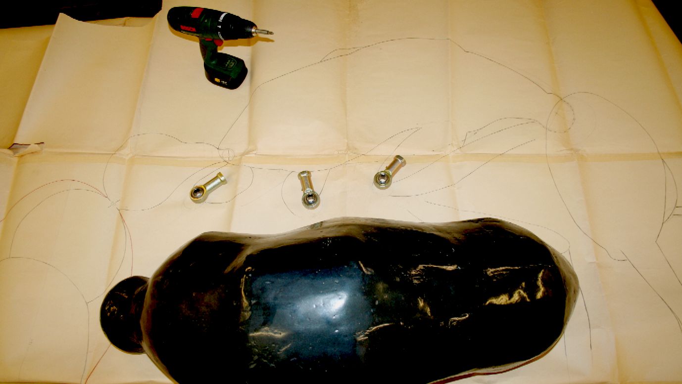
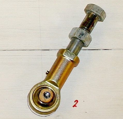
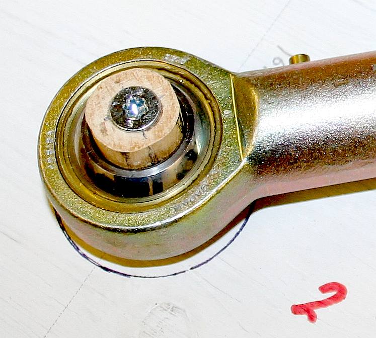
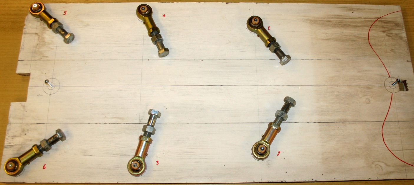
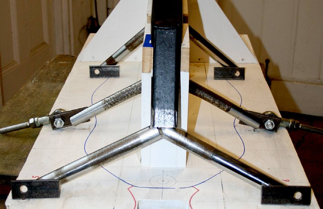
LEG JOINTS - Heavy duty spherical rod ends are used for the leg (hip) joints. These can take several tons each. A wooden peg that fits tight inside the bore of the stainless steel ball is screwed to the base. The peg rotates slightly off centre to allow us to position precisely. This gives us an accurate position when it comes to assembly before welding of the chassis. These joints are expensive, but last a long time. They even have grease nipples and can be ordered with rubber shrouds. They will have to be modified for our purposes with another rod welded onto the opposite end to the screw threaded section. NOTE: Spherical joints are not as controllable as hinge joints. You have to be careful when designing a robot to use the best joint for the job.
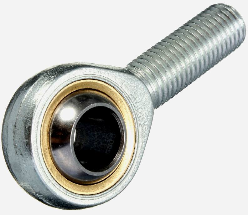
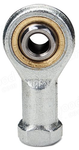
Other joints that are to be used in this robot include the 14 and 6mm rod ends shown above. The 6mm [right] spherical joints are particularly suited to control applications.
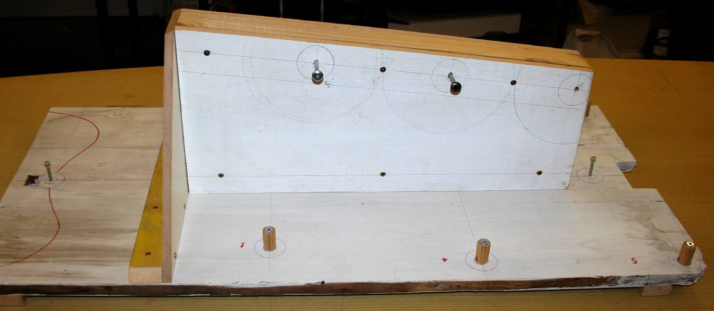
PRODUCTION JIG - A base for the jig is accurately marked out on a 25mm softwood base. Next comes a support for the steel box section frame (not yet shown). The legs joints are in situ, with the head and tail joint centers marked with circles and a screw. These are the hard points of the working mechanics. Unlike most animatronic displays, this robot will be able to walk autonomously, lift heavy objects and even stand guard. Please note that this photograph is copyright © Jameson Hunter Ltd 2015. You will need permission from Jameson Hunter to be able to reproduce it.
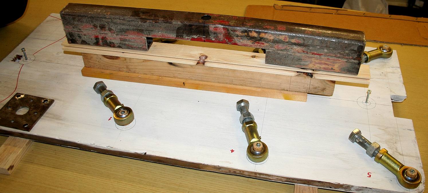
STEEL FRAME - From the base board we can build up a central block to support the steel backbone at the correct height. From here we can insert the subframes for each of the six hip joints. The movement (bearings, spindles and gears) will be mostly coming from underneath this solid section. We are using steel that is thicker than needed for the prototype - just in case adjustments are necessary. Unlike wood, if you get something wrong in steel, it is no big deal to grind out the mistake and weld in another section.
In the case of a robot with a hydraulic movement, the square section (RHS = Rolled Hollow Section) tube will be replaced by a circular section tube, to be able to act as a pressurized fluid reservoir. This little beauty is going to be one tough mother. Compare this frame with the frame of Stompy below; a 6 ton hexapod being built in the USA. Please note that this photograph is copyright © Jameson Hunter Ltd 2015. You will need permission from Jameson Hunter to be able to reproduce it.
JIG DEVELOPMENT - Alignment of the leg bearings to the driving cranks is essential. The only way to achieve this time and time again is to make sure that your jig is accurate - to cabinet making standards. You can see above that the pine planking has been reinforced underneath and braced on top. The angle of the flat timber top is that of the backbone of the chassis/frame. This robot is a vehicle of course, so 'chassis' may be more correct than 'frame.' Please note that this photograph is copyright © Jameson Hunter Ltd 2015. You will need permission from Jameson Hunter to be able to reproduce it.
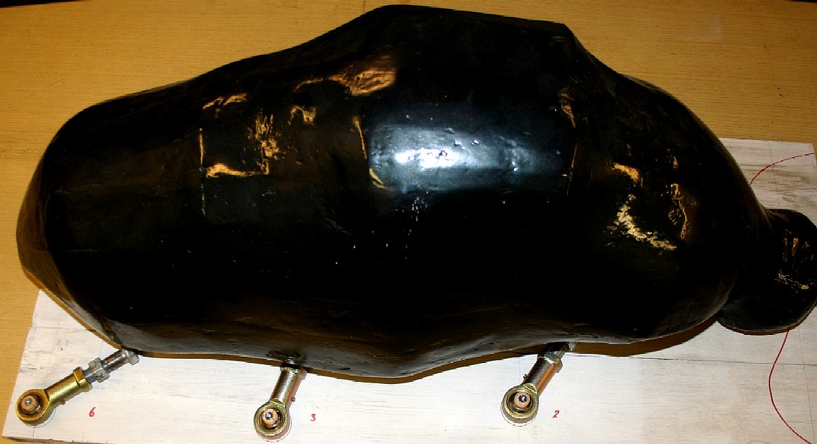
POSITION CHECK - The ant body is placed over the top of the jig to check clearances. Please note that this photograph is copyright © Jameson Hunter Ltd 2015. You will need permission from Jameson Hunter to be able to reproduce it.
LAYOUT - We could not resist doing a quick mock-up and are pleased that even this is starting to look like the real bulldog ant. The steel version of the frame will be a standard platform that will be made available to schools, museums and other operators for around £500 pounds ($750 dollars). That gives you a 2.4m (8' foot) hexapod (9' [2.7m extended stretch] and legs for you to makes your own bodywork and static display unit. If you'd like this bodywork in GRP add another £200 pounds ($300 dollars). We are seeking best prices for parts at the moment - so be aware that these prices are ballpark.
If you'd like the robot programmed to interact with an audience, we can also arrange that for you, but at more cost. Please note that this photograph is copyright © Jameson Hunter Ltd 2015. You will need permission from Jameson Hunter to be able to reproduce it.
WALKING - The budget movement will be a basic variable track system with independent transmissions on the left and on the right driven by medium sized DC motors. This is suitable for radio control, with a human operator. A more advanced movement will involve hydraulic actuators and a degree of artificial intelligence, to include object recognition. We could also include GPS tracking - but what for, we have no idea, other than as an anti-theft device.
MILITARY - Under no circumstances may our products be used by any military or law enforcement organization, for any warlike or crowd control purposes. Anyone purchasing one of these units will be required to sign a binding undertaking (Deed) to that effect. Any unit found to have been purchased by proxy, will be confiscated, along with civil remedy in respect of breach of contract, that all parties in the chain will be liable for - to include damages for vehicles developed from our designs without our consent.
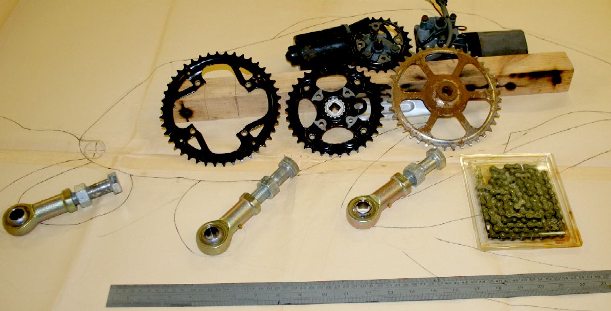
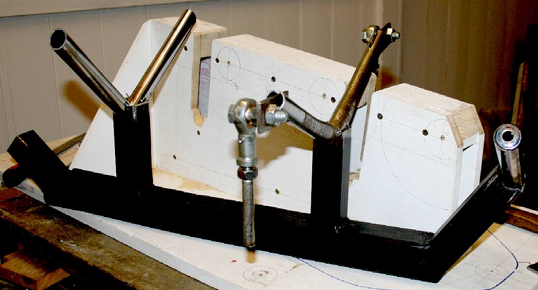
TRANSMISSION - For this prototype we are experimenting with a lot of stuff in the workshop, before committing to a production specification. In this photograph you can see how we worked out the basic layout, using real components laid onto a full size drawing. From this point on detail design will be using AutoCad computer aided design software. It is though great fun experimenting like this on the hoof - and it saves days of design time. Please note that this photograph is copyright © Jameson Hunter Ltd 2015. You will need permission from Jameson Hunter to be able to reproduce it.
TECHNICAL DRAWING - It is vital that any design engineer can draw to scale and to exacting standards, using basic instruments, a ruler, set square and compass. By all means use computers to assist the design process, but in the end and especially when prototyping, steel has to be measured and cut - so to aluminium sheet, plywood, etc. The only way to do this is to loft the designs onto whatever material is being cut, by hand. Plastic printing is fine for parts that are not highly stressed, or very large. In this picture some of the machine parts are placed on a working drawing to make sure the clearances are good - they are. Please note that this robot is Design Copyright and that this photograph is copyright © Jameson Hunter Ltd 2015. You will need permission from Jameson Hunter to be able to reproduce it.
MILITARY RESTRICTION - Under no circumstances may our products be used by any military or law enforcement organization, for any warlike, combat, or peacekeeping crowd control purposes. Anyone purchasing one of these units will be required to sign a binding undertaking (Deed) to that effect. Any unit found to have been purchased by proxy, will be confiscated, along with civil remedy in respect of breach of contract, that all parties in the chain will be vicariously liable for - to include damages for vehicles developed from our designs without our consent - and possible fraud issue from the deception. In addition to copyright theft, the law of passing-off applies.
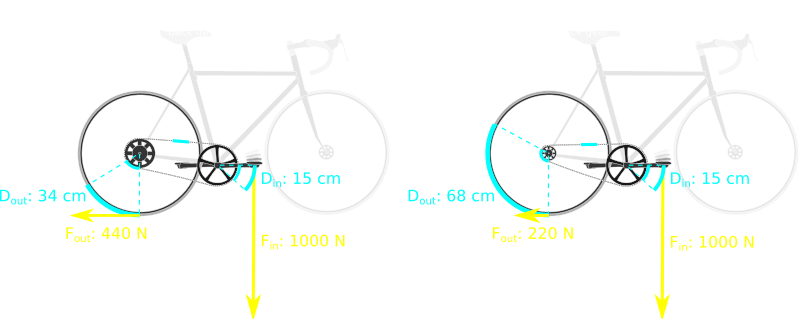
LEVERAGE - [LEFT] the gear is low (1st) providing good acceleration and traction up hills. [RIGHT] the gear is high (5th) providing a higher speed, having accelerated through the gears.
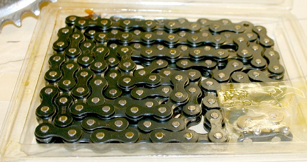
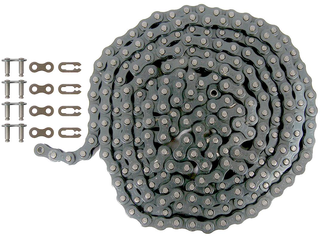
CHAIN DRIVE - Chain drive is still one of the most efficient ways of transmitting movement. Chains are typically 95% efficient - hard to beat. We could have the chains running in an oil bath, but with the limited mileage these units are likely to see, that might be overkill.
A bicycle chain can be very energy efficient: one study showed efficiencies as high as 98.6%. The study, performed in a clean laboratory environment, found that efficiency was not greatly affected by the state of lubrication. A larger sprocket will give a more efficient drive, reducing the angular change of direction of the links. Higher chain tension was found to be more efficient.
The chain in use on modern bicycles has a 1/2" (=12.7 mm) pitch, which is ANSI standard #40, where the 4 in "#40" indicates the pitch of the chain in eighths of an inch, and metric #8, where the 8 indicates the pitch in sixteenths of an inch.
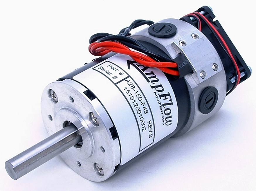
MOTORS - Where you can't beat China for price, the above is a selection of mid-range priced, higher output motors from a US robotic supply site for 12-48 volts. From left to right: 2.1hp ($109), 4.6hp ($339) and 7.8hp ($449) DC brushed motor variants. The four brushed design on the right uses rare earth magnets and has forced air cooling. Speed controllers will be around another $450.
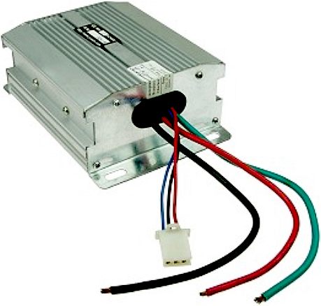
CONTROL: 48V 1500W Electric Scooter Speed Controller - Designed for 48 Volt DC electric scooter and bike motors up to 1500 Watts. Recommended motor size 1000W-1500W. Can be used to power two 500W-750W motors simultaneously. Maximum current 45 Amps. Under Voltage protection 41 Volts. Current limiting feature prevents controller damage due to over-current conditions. Under voltage protection feature prevents over-discharge and extends battery life. Compatible with all standard 3-wire variable speed hall-effect throttles. Item # SPD-481500 $79
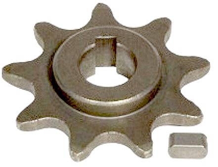
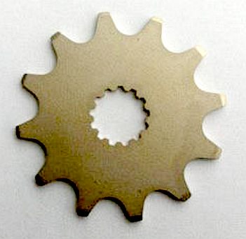
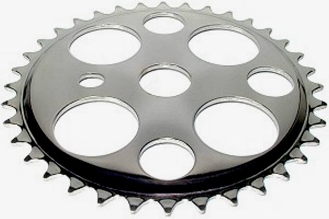
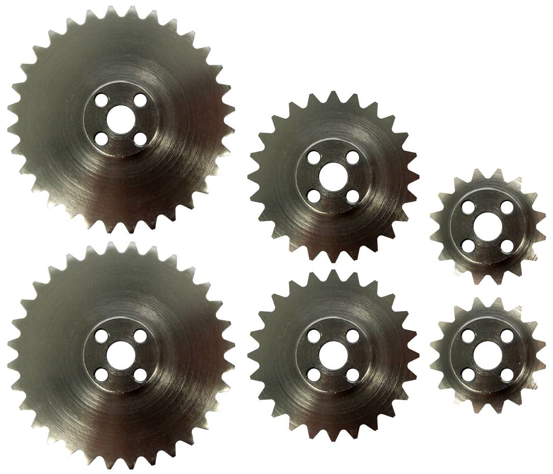
SPROCKETS - The number of teeth on drive and driven sprockets determines the gear ratio. Fewer teeth are normally on the motor sprocket of electrically driven bikes, whereas with pedal powered bicycles, the reverse is true, there are fewer teeth on the driven (wheel) sprocket. Many robots use chain and sprockets as the means to achieve movement. The sprockets above are 9, 12 and 36 teeth.
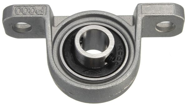
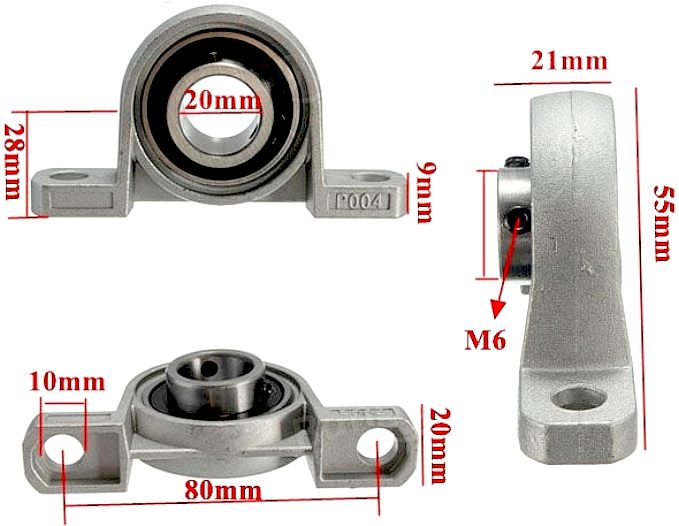
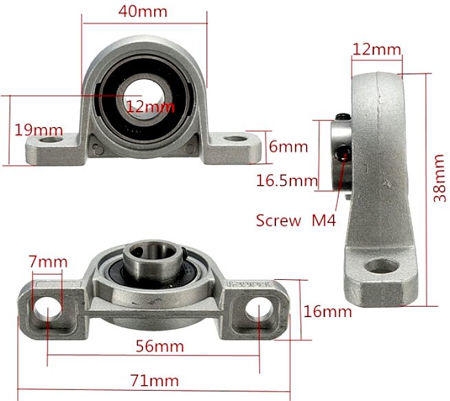
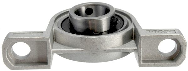
BEARINGS - We are using 12 of these 10mm ball-bearing (pillow mount) blocks to carry the shafts that the drive sprockets bolt onto. You need two bearing blocks for each shaft and each shaft only carries one of the drive sprockets. The good news is that they are not overly expensive. Larger ball-bearings mean higher load carrying capacity at the expense of more drivetrain rolling-resistance losses - in this case, quite a bit from the bearing grease.
MORE BEARINGS - We'll be using 12, 15, 20 and 25mm ball-bearing (pillow mount) blocks on other parts of the production DinoBots.
ROUGH LAYOUT - The jig allows us to visualize how the mechanical parts will work together. As such it is a major design tool and a time saver.
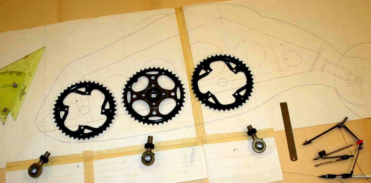
CHAINS & SPROCKETS - So here we are, three sprockets in the correct positions. These sprockets cannot be used as they are. We will be making reinforced centre plates and only using the teeth as ring-gear. The geometry of the cranks is critical to efficient walking - and even more so for running. PTFE bearings are bound to come into the frame - although we will be trying out nylon as well and a whole host of lubricants. Please note that this photograph is copyright © Jameson Hunter Ltd 2015. You will need permission from Jameson Hunter to be able to reproduce it.
Polytetrafluoroethylene (PTFE) is a synthetic fluoropolymer of tetrafluoroethylene that has numerous applications. The best known brand name of PTFE-based formulas is Teflon by DuPont Co., which discovered the compound.
PTFE has one of the lowest coefficients of friction against any solid.
COMPLICATED
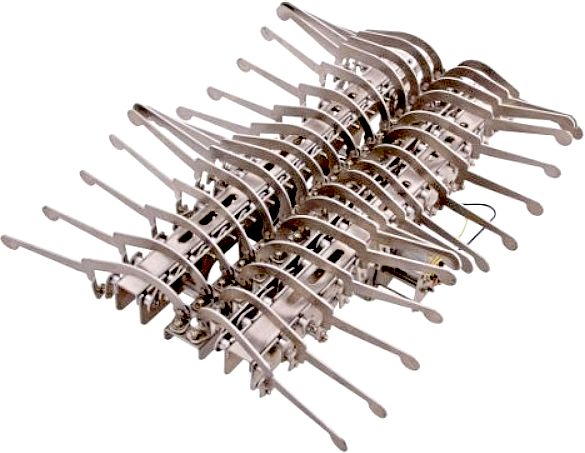
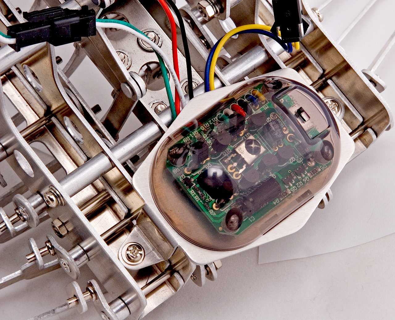
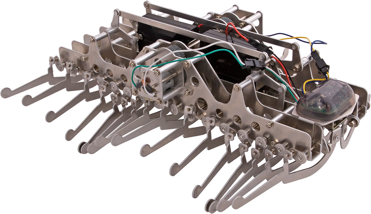
- The Gakken Mechamo centipede robot is guaranteed to freak your mom out should she stumble upon it by accident while clearing out your room.
Measuring approximately a foot long (300mm), this battery guzzler (how can it not be
when there are 32 legs moving simultaneously) moves just like a real
centipede - only really slowly. It will probably annoy everyone else in the house (and your neighbors living downstairs if you’re at an apartment)
with the sound that it makes whenever it moves across the floor. Retailing for $99.95, the Mechamo centipede robot comes with a wireless
remote control and will probably require a fair amount of gray matter to put
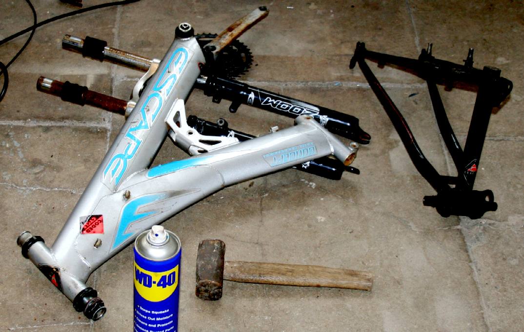
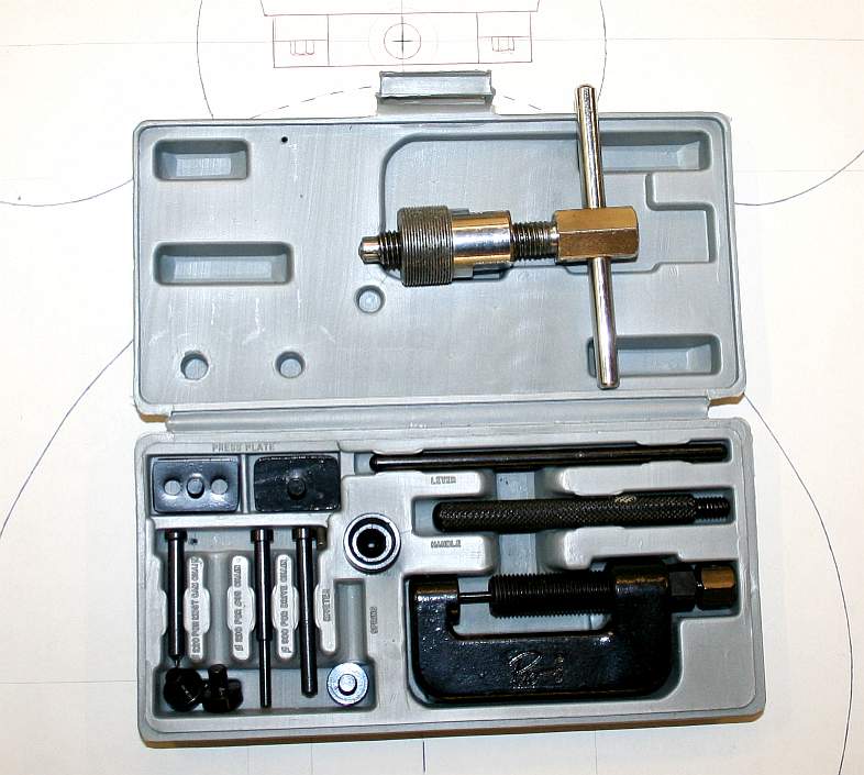
SALVAGE - Recycle that cycle - rather than experiment with new parts, we are using using recycled parts from many redundant machines and bicycles. Some of the bearings, steel and sprockets came from push-bikes. When you have a rig that works well, of course, use new parts that may have a higher specification. The steel and alloy parts of bicycles are relatively high quality - because a bike has to be light and functional - just like a robot. The Wright Brothers were cycle makers. They used their bicycle making skills to create an aircraft that flew at Kitty Hawk in the US. Do not therefore underestimate the design effort that has gone into bicycles. When disassembling a push bike for parts, be sure to use the correct tools. If you don't use the correct tools you are likely to injure yourself and damage the parts. Safety first! For taper-fit cranks you will need a threaded extractor tool and for chains a link-extractor, seen here on the right. Modern bike chains do not have the split links that were common in years gone by - because of the potential weakness = the weakest link : )
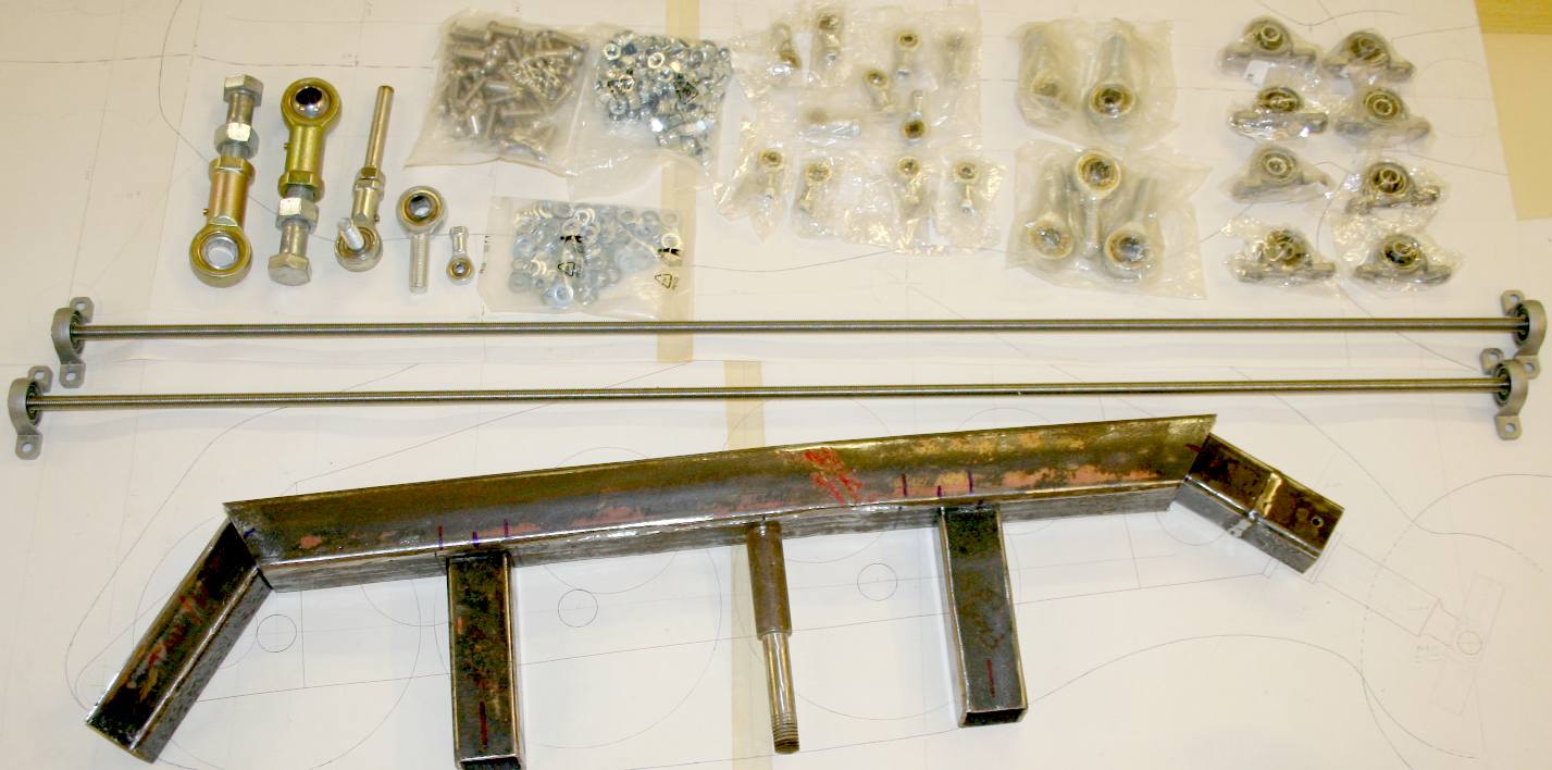
PARTS - December 19th, a whole lot of parts arrived today from Germany, thanks to the Royal Mail doing their bit. You can see the pillow bearings on the right, a whole swatch of spherical rod ends and packets of nuts and bolts, which came from Screwfix and Toolstation locally in Eastbourne. A robot uses a lot of parts. In this case the assembly time is small and the frame is simple. Please note that this frame is Design Copyright and that this photograph is Copyright © Jameson Hunter Ltd 20 December 2015. All rights reserved. You will need permission from Jameson Hunter to be able to reproduce it.
WORK DONE
Walking takes energy, or power, in this case energy stored in a battery in electrical form. We can measure the energy stored and work out the energy needed to walk because we know that one horse can lift 550lbs, one foot in one second. We also know that 746 watts of electrical energy is equivalent to one horsepower. From this basic information we can calculate the energy in watts we need to walk at a given speed. Unfortunately, it all gets rather messy with an SI measure called "joules" creeping in - used to measure work done. You can ignore joules for now, but should you want to know for later:
Energy E in joules (J) is equal to the power P in watts (W), times the time period t in seconds (s): E(J) = P(W) × t(s). 1 joule is equal to 1 newton meter, or 0.737562149277 foot-pounds of force, or one foot-pound force = 1.35581794833 newton-meters.
Pounds or Newtons of force need to be qualified to know that certain machines are powerful enough to do the job they are designed for, such as crushing strength in the jaws of this robot. But on this page we are concerned with walking - and for walking calculations we simply need to know what weight we are moving and how fast we want it to travel.
We
can ignore acceleration, but a quick word on that. Sports announcers will occasionally say that a person is accelerating if
they are moving fast. Yet acceleration has nothing to do with going fast. A person can be moving very fast and still not be accelerating. Acceleration has to do with changing how fast an object is moving. If an object is not changing its velocity, then the object is not
accelerating - it is of course still traveling along.
For example, a car accelerates from 25m/s to 35m/s in 5 seconds. In doing so its velocity changes by 35 - 25 = 10m/s. So its acceleration is 10m/s divided by 5 = 2m/s2 (or 2 meters per second for every second). We will though ignore acceleration, because the robot is not going to travel very fast it does not need to accelerate quickly.
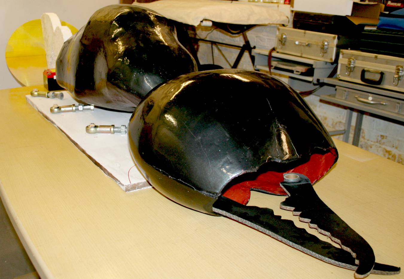
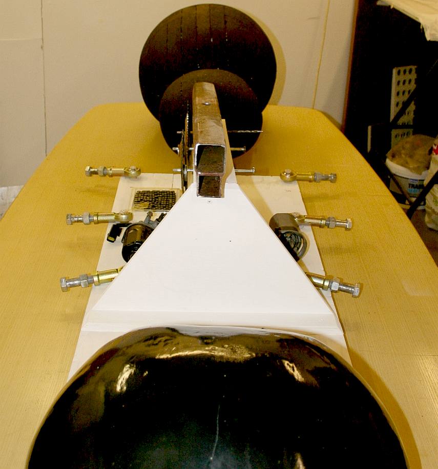
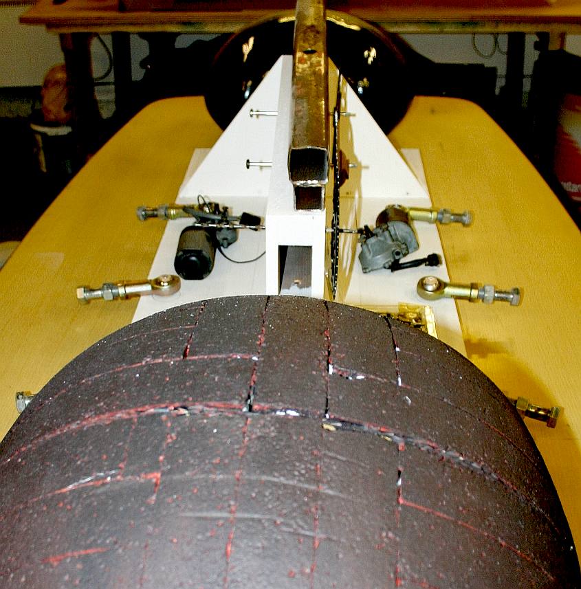
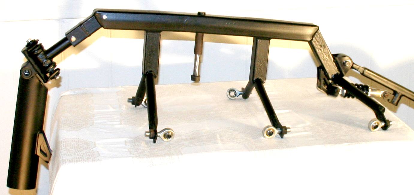
OVERVIEW - These are views from the head to the tail and from the tail to the head. We take pictures like this for later reference purposes. We suggest that you do the same for any of your projects. You will know why when something goes wrong. It always helps to be able to back track during design and assembly. Please note that this photograph is copyright and the ant robot is design copyright © Jameson Hunter Ltd 2015. You will need permission from Jameson Hunter to be able to reproduce the photograph and may be prosecuted or taken through the civil courts if you infringe any of the company's intellectual property rights. It is far better to ask for any permissions. You will find this company to be most accommodating.
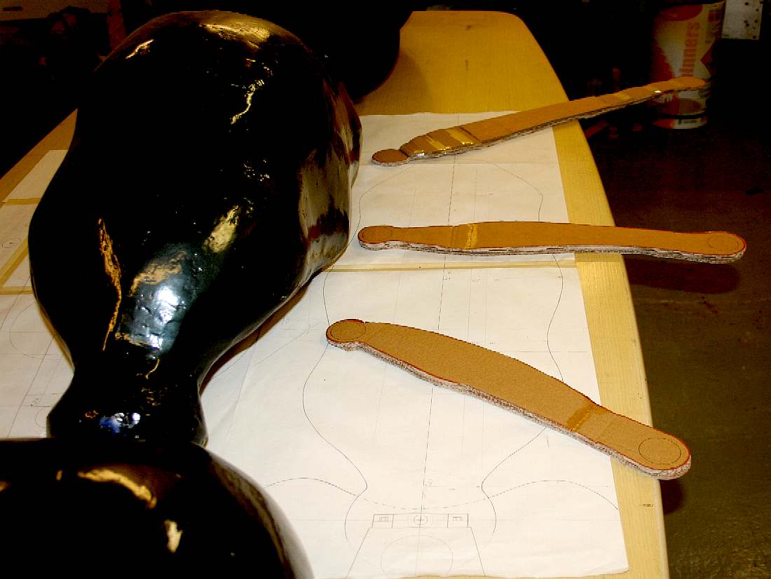
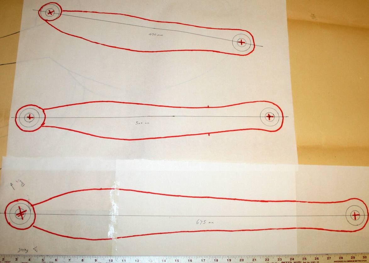
LEG DRAWINGS - Insects are complex animals. Note here that each thigh of the six legs is a different length. That means that the gearing of each leg will change for a smooth walking cycle - and then again the connecting rods will be different lengths and at different angles. Where's the ibuprofen when you need it? They are also handed, meaning that the left hind leg is a mirror image of the right hind leg, but they are not the same. That means making six separate leg moulds for the composite versions. We will be carving in wood at first, to make the master for the moulds.
GEOMETRY - Careful design of the leg is important if we are to avoid another actuator for the lower leg. We are thinking about a two-stage spring loaded system at the moment - with shock absorption. Amputee athletes use a similar system for high speed track events. Please note that this photograph and the subject drawing are copyright © Jameson Hunter Ltd 2015. You will need permission from Jameson Hunter to be able to reproduce it.
MAKING THE DEVELOPMENT LEGS IN ALUMINIUM
We will be making the first set of legs in 16 gauge aluminium tubing that is far more sturdy than any tubing we might use for a high speed version. Using a relatively generous wall section will make joints and connections more tolerant - and we can overload the chassis - though we may use strain gauges to see what is happening when the going gets tough.
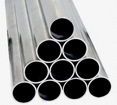
Aluminium alloy 6063 is a versatile, medium strength alloy, commonly referred to as an architectural alloy. It is normally used in intricate extrusions. It has a good surface finish, high corrosion resistance, is readily suited to welding and can be easily anodised. Most commonly available as T6 temper, in the T4 condition it has good formability. 6063 is typically used in: Architectural applications, Extrusions, Ladders, Window frames, Doors, Shop fittings and Irrigation tubing. 6063 aluminium is also finding applications in hydro-formed tube for vehicle chassis.
Our preferred supplier is Aluminium Warehouse, which company offers a friendly, efficient service within the United Kingdom and simply superb packaging as you can see for yourselves in the picture below. We chose a wide selection of diameters to be able to experiment for best results, from 3/4 inch (19mm) to 1 5/8 inch (41mm) with 1 inch (25.4mm) and 1 3/8 (35mm) inch steps.
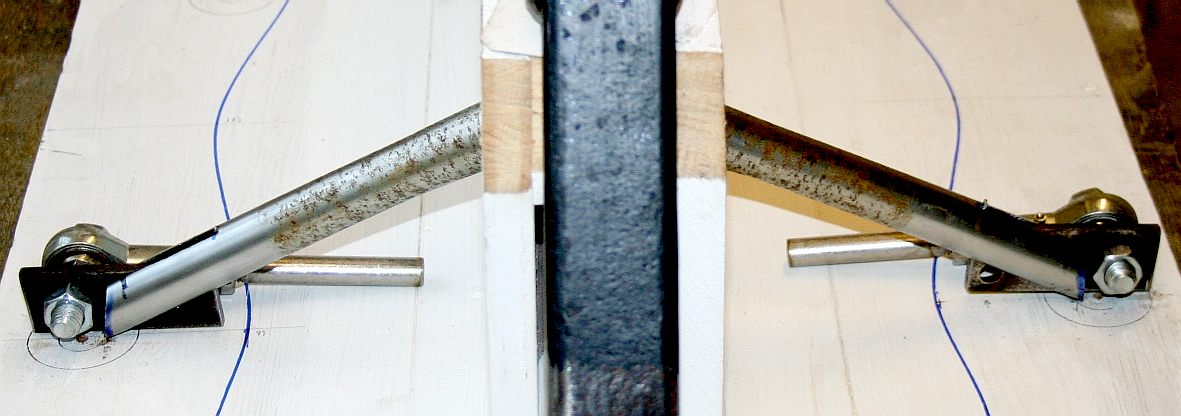
AXLE MOCK UP - December 27th - More progress. Working in steel is time consuming when prototyping demands constant fine adjustments. Once the angles are all worked out it is not so bad - working them out means many cups of tea and coffee - to gather ones thoughts. Please note that this frame is Design Copyright and that this photograph is Copyright © Jameson Hunter Ltd 20 December 2015. All rights reserved. You will need permission from Jameson Hunter to be able to reproduce it.
AXLE FITTING - December 30th - The axle tubes are slotted into place. They need to be an interference fit ready for welding. This frame is made of steel. For a robot land speed record run, an upgraded titanium unit will be used. Please note that this frame is Design Copyright and that this photograph is Copyright © Jameson Hunter Ltd 20 December 2015. All rights reserved. You will need permission from Jameson Hunter to be able to reproduce it.
TRANSMISSION - The bare frame now needs the transmission added. Please note that this frame is Design Copyright and that this photograph is Copyright © Jameson Hunter Ltd 27 January 2016. All rights reserved. You will need permission from Jameson Hunter to be able to reproduce it.
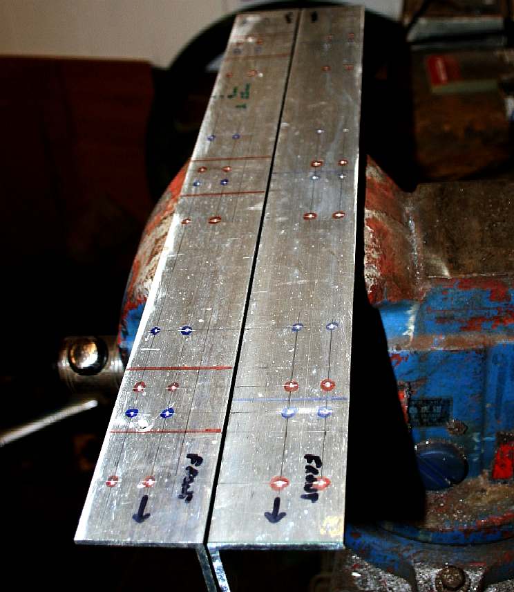
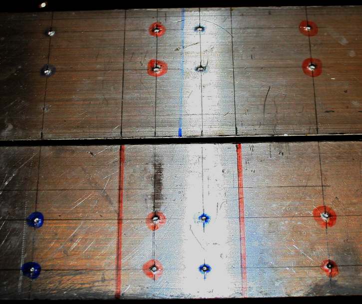
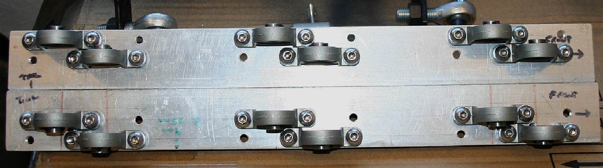
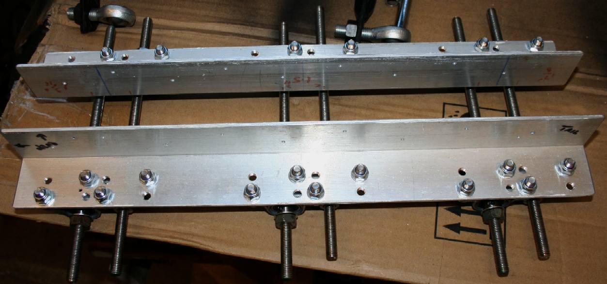
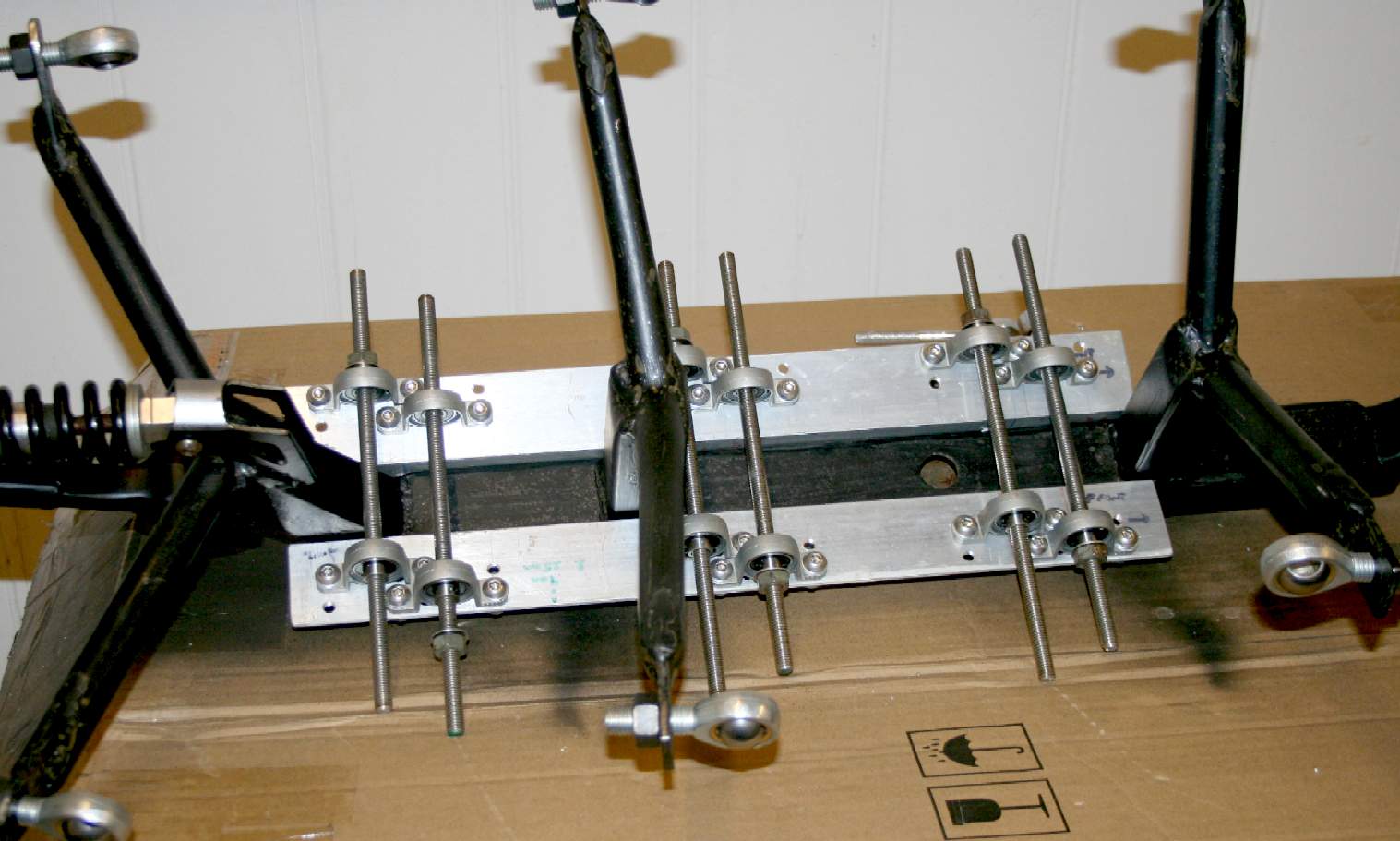
DRIVESHAFTS - February 11 - 6063 grade aluminium angle forms the base for a modular driveshaft bearing block assembly. With any hand built machine, careful marking out is the key to quality assembly, though we are building in a high degree of self alignment with pillow ball-bearing blocks. Note the colour coding - where a second set of drillings is included just in case we need to change the layout later.
Please note that this frame is Design Copyright and that this photograph is Copyright © Jameson Hunter Ltd 11 February 2016. All rights reserved. You will need permission from Jameson Hunter to be able to reproduce it.
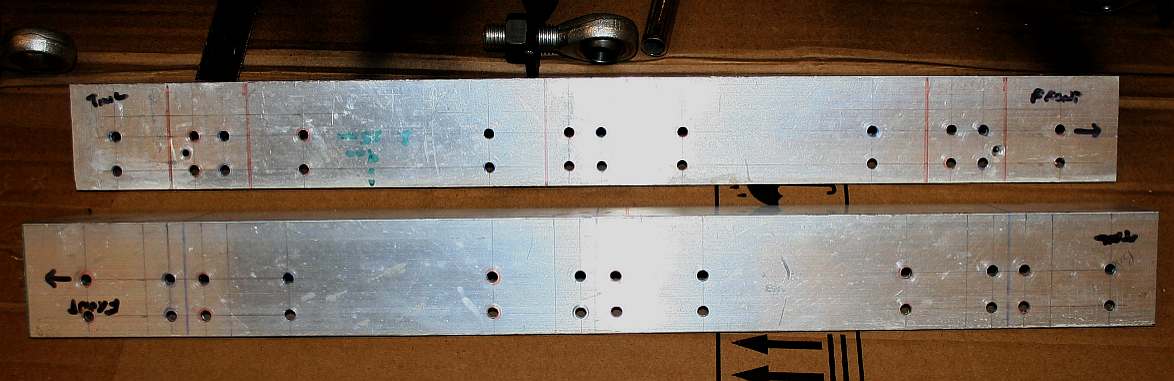
BEARING CARRIERS - February 11 - Forty-eight drillings later, and the alloy angle looks like this. Each leg of the robot has a separate driveshaft and carrier bearings. The shafts are offset, making the angles for each leg crank unique. Automotive terminology is mixed with biological anatomical names throughout this project, to make it easier to understand the application of mechanics to replicate a living thing. That is what animatronics is all about.
Please note that this frame is Design Copyright and that this photograph is Copyright © Jameson Hunter Ltd 11 February 2016. All rights reserved. You will need permission from Jameson Hunter to be able to reproduce it.
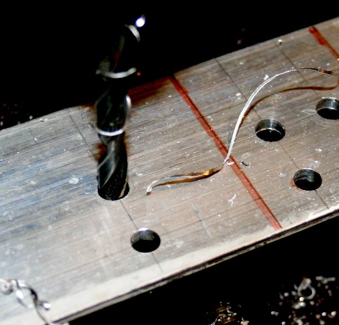
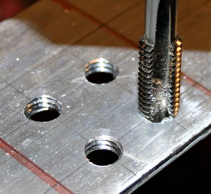
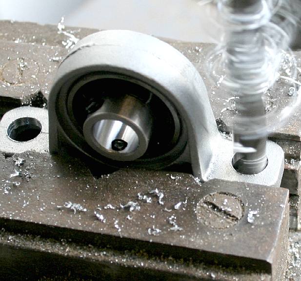
MAKING A THREAD - February 11 - Working our way up through drill sizes, until finally we get to a size where an 8mm tap will cut a perfect thread. 6063 alloy machines nicely. You can use an ordinary pillar drill for this. Production units will be machined using CADCAM computer controlled equipment for speed and accuracy. There are not so many highly skilled manual workers these days, because of robotic manufacturing.
Please note that this frame is Design Copyright and that this photograph is Copyright © Jameson Hunter Ltd 11 February 2016. All rights reserved. You will need permission from Jameson Hunter to be able to reproduce it.
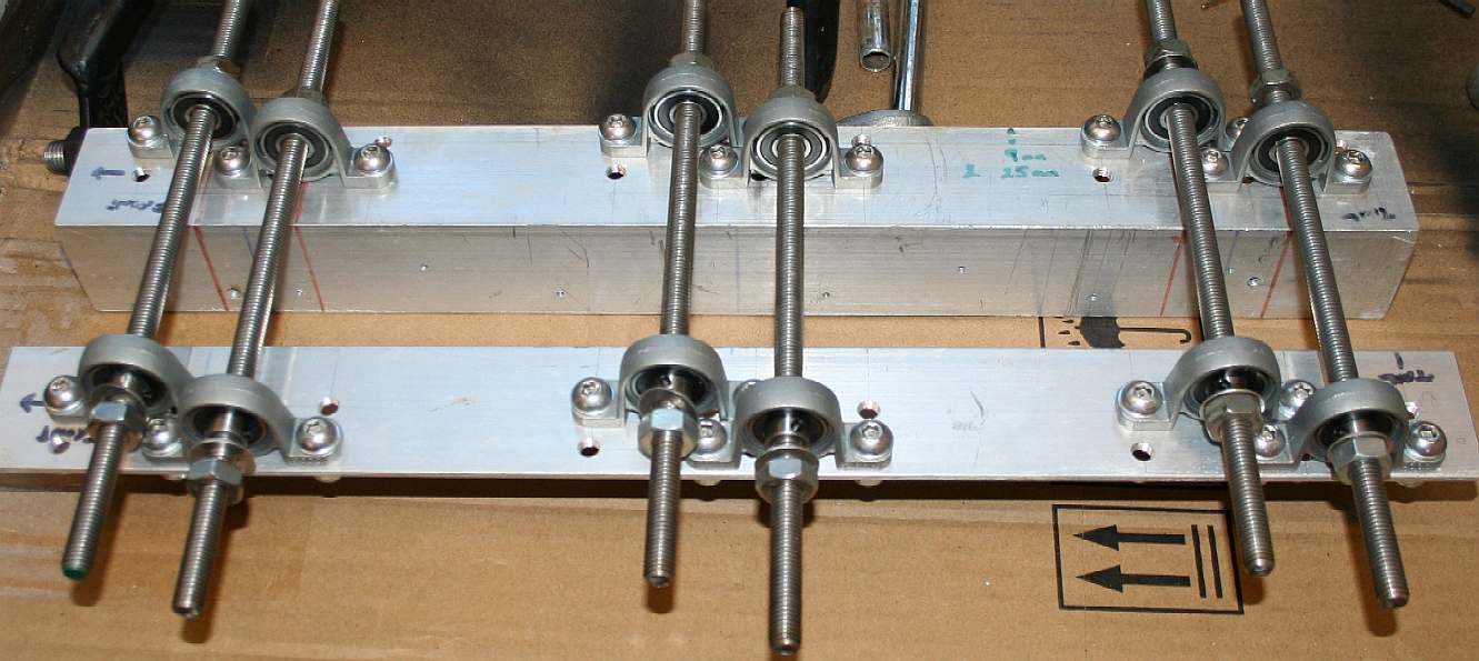
PILLOW BLOCKS - February 11 - The mounting holes needed to be drilled out slightly to match our stainless steel bolts. The fit had to be tight with just enough play to make assembly easy, but not compromising the integrity of the structure mechanically.
Please note that this frame is Design Copyright and that this photograph is Copyright © Jameson Hunter Ltd 11 February 2016. All rights reserved. You will need permission from Jameson Hunter to be able to reproduce it.
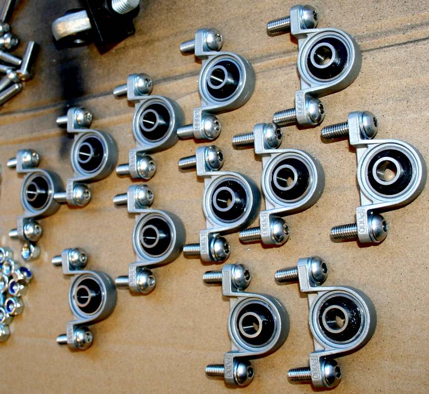
GETTING YOUR BEARINGS - February 11 - Twelve blocks later, and the washers and bolts could be pushed into place in what looks like an army of ants. Please note that this frame is Design Copyright and that this photograph is Copyright © Jameson Hunter Ltd 11 February 2016. All rights reserved. You will need permission from Jameson Hunter to be able to reproduce it.
ASSEMBLY - February 11 - There is something satisfying about assembling a mechanical component. It is just like a jigsaw puzzle, putting all the pieces in the right place. That is what design is all about. You create the concept, design the parts to fit into your robot - and make them according to specification. It should come as no surprise that it all fits together, but you may find a few teething issues. Almost no engineering project completes without modifications here and there. So, don't get upset when things don't go together exactly as envisaged first time. It is quite normal. Teething only becomes an issue when the fundamental design is flawed. That rarely happens these days, but even the likes of Ferrari have had moments where they got it wrong on the drawing board. Enzo Ferrari once built a whole car only to find the engine was longer than expected. He was not happy that day! Test fitting though time consuming, is generally worth the bother. Ferrari had to lengthen the chassis to shoehorn the V12 beastie into that particular car.
Please note that this frame is Design Copyright and that this photograph is Copyright © Jameson Hunter Ltd 11 February 2016. All rights reserved. You will need permission from Jameson Hunter to be able to reproduce it.
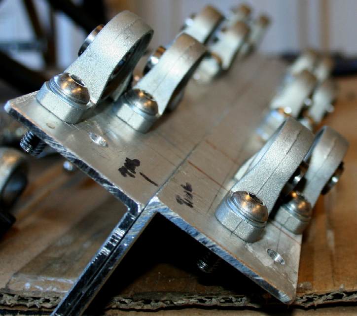
TIGHTENING SEQUENCE - February 11 - When tightening bolts into aluminium do not over tighten. If in doubt use a torque wrench. This sub-assembly is not a cylinder head where absolute evenness is required to prevent distortion and so compression leaks, but our engineers are just as careful. Having tightened correctly, the lock-nuts are fitted to the back to prevent undoing under load and vibration. Please note that this frame is Design Copyright and that this photograph is Copyright © Jameson Hunter Ltd 11 February 2016. All rights reserved. You will need permission from Jameson Hunter to be able to reproduce it.
DRIVE SHAFTS - February 11 - Six stainless steel shafts are cut in rough from threaded section. These will need to be cut down to size later, but it is better to have a little extra when assembling a transmission for the first time. You will note from the picture above that an extra set of threads were cut just in case shaft reversal is to be tried. Please note that this frame is Design Copyright and that this photograph is Copyright © Jameson Hunter Ltd 11 February 2016. All rights reserved. You will need permission from Jameson Hunter to be able to reproduce it.
DRIVESHAFT FITTING - February 11 - The shafts now need spacers and washers for a perfect fit - and of course smooth running. Before that, we need to bolt the sub-frame to the main chassis. Please note that this frame is Design Copyright and that this photograph is Copyright © Jameson Hunter Ltd 11 February 2016. All rights reserved. You will need permission from Jameson Hunter to be able to reproduce it.
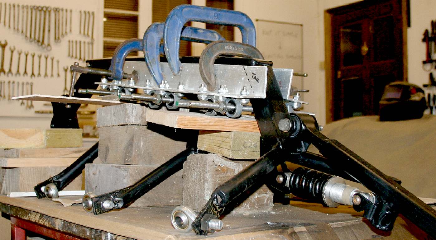
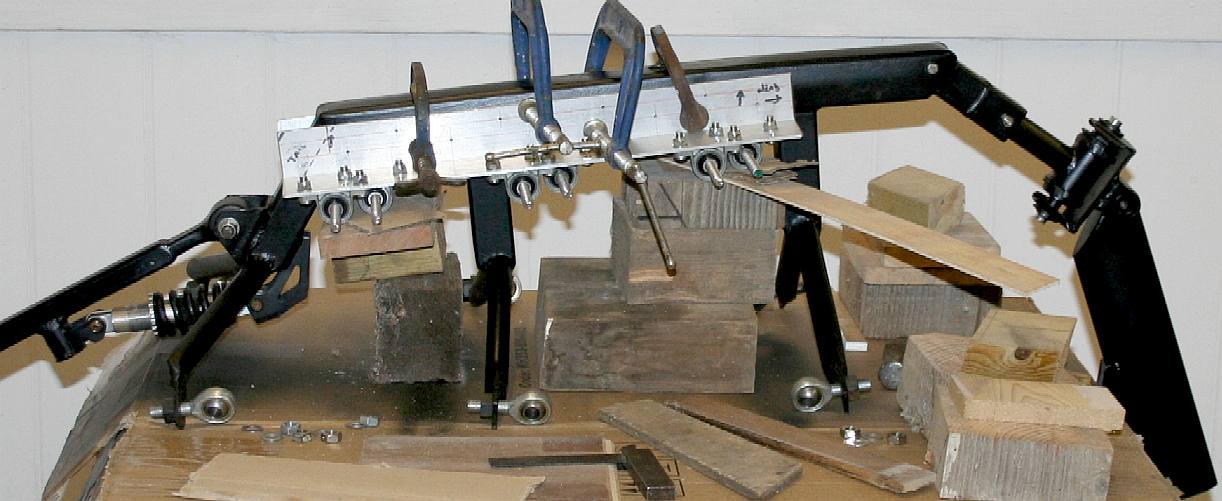
RIGHTY HO THEN - February 11 - In the words of Ace Ventura, it is time to mate the bearing subframe with the main frame. We could have done this using the timber buck, but then the shafts would not be in place. To be sure of alignment, we decided to jig the assembly using wooden blocks and inserts that we keep especially for such (traditional) procedures. Do not clamp tight. Use a soft mallet to tap into position incrementally. Check alignment with set squares, and only when satisfied, mark to drill the pilot holes. Please note that this frame is Design Copyright and that this photograph is Copyright © Jameson Hunter Ltd 11 February 2016. All rights reserved. You will need permission from Jameson Hunter to be able to reproduce it.
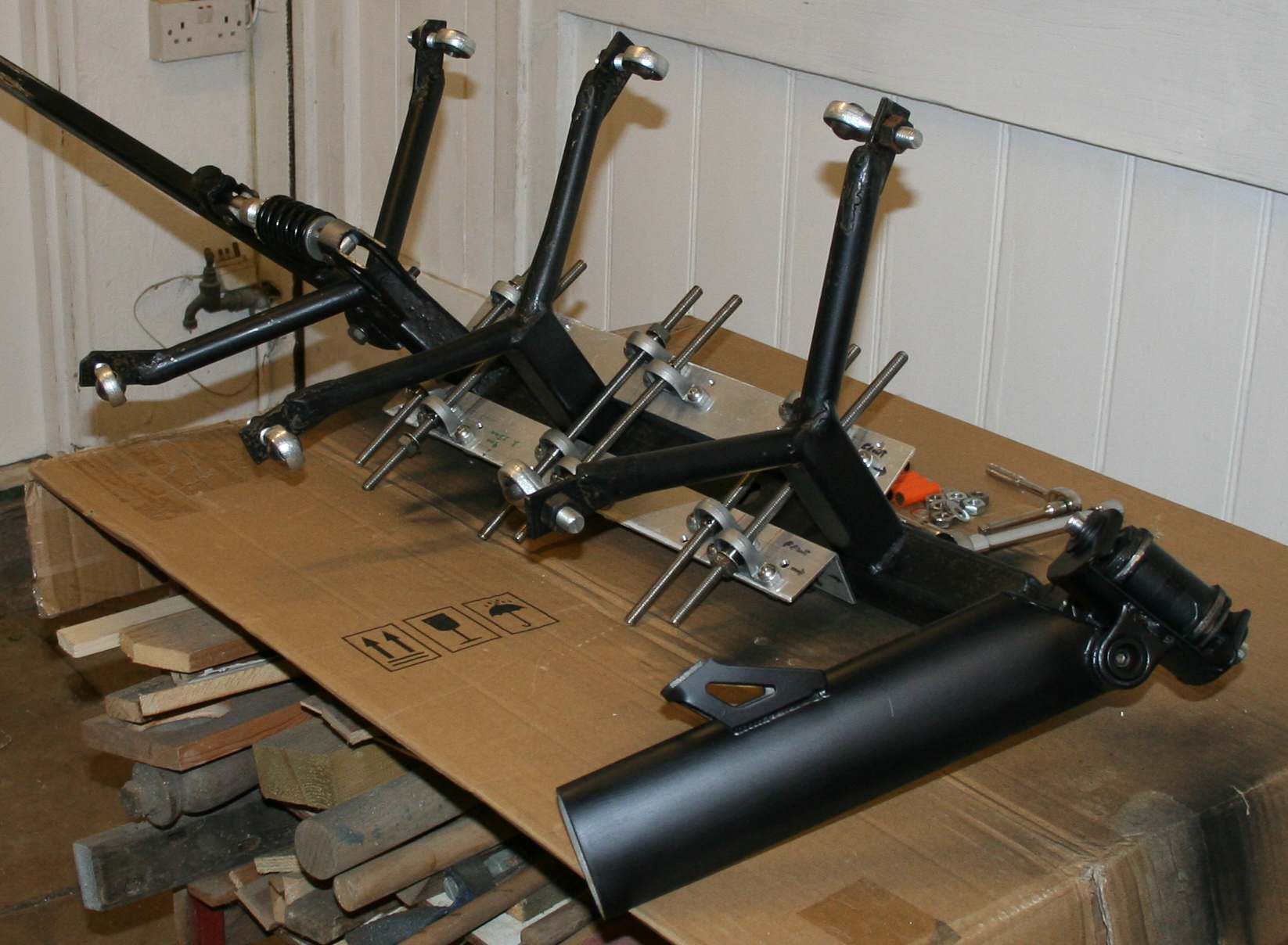
DINOBOT - February 11 - Dino looks a little sad here with its head pointing to earth. The subframe is aligned with clearance for all six shafts. Using recycled steel for the mainframe meant some compromise. On production models fresh box section will make manufacture a whole lot easier. Please note that this frame is Design Copyright and that this photograph is Copyright © Jameson Hunter Ltd 11 February 2016. All rights reserved. You will need permission from Jameson Hunter to be able to reproduce it.
BOLTED - February 11 - Drilled and bolted together, we can invert Dino to custom fit the driveshafts. They need spacers and cutting down, with bolts on either side of the load bearings. Please note that this frame is Design Copyright and that this photograph is Copyright © Jameson Hunter Ltd 11 February 2016. All rights reserved. You will need permission from Jameson Hunter to be able to reproduce it.
ARTICULATION - February 11 - Inverted like this Dino looks like a pet submitting to its master. Once the spacers are fitted, the driven cogs can be bolted to their respective shafts and chain fitted to the test drive motors. Please note that this frame is Design Copyright and that this photograph is Copyright © Jameson Hunter Ltd 11 February 2016. All rights reserved. You will need permission from Jameson Hunter to be able to reproduce it.
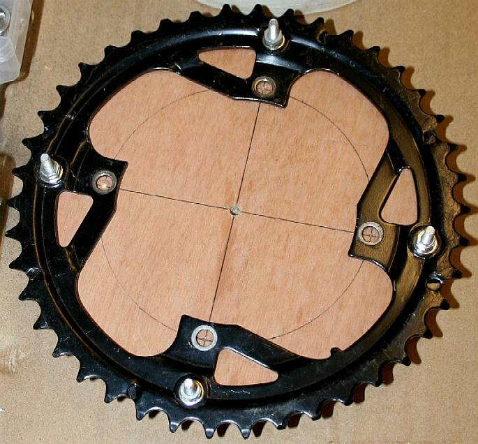
PLYWOOD - Cutting plywood blanks from a sheet of 18mm (roughly 3/4") sheet. We need six of these laminated discs. They could be finished on a lathe to ensure concentricity, but we are at the experimental stage, so for speed and economy, we'll smooth the edges on a belt sander by hand, since steel ring gear is to be bolted to the plywood body in any case, hence the real issue is accurate marking out. Production units could be laser cut.
WOODEN BLANK - The blank was marked out before cutting so that ninety degree divisions were easy to define. Being a natural material, you may find it more difficult to drill holes where you want them in wood, than with steel or aluminium. Grain irregularities sometimes deflect a thin drill. We use a compass needle to pinpoint a drilling, and then a really fine centre punch ground especially to achieve a deep penetration from the fine entry. No good of course for steel. If a fine drill hits a hard spot (causing deflection), change for a thicker drill and be sure that the distance from the chuck to the work piece is as short as possible to prevent angular change as much as possible.
RING GEAR - The steel sprocket is bolted to the plywood body to make a rigid unit. This in turn is bolted to the shaft with suitable washers to spread the loads. There is a lot more engineering to come involving this composite sprocket. We need to include offset bearings into which the crankshaft fits for an efficient transfer of energy. These hybrid bearings could be bolted on rather than machined into the plywood. Using plywood gives us a more rigid assembly with weight savings. Wood is also cheaper than aluminium or other composites.
Please note that this transmission is Design Copyright and that this photograph is Copyright © Jameson Hunter Ltd 13 February 2016. All rights reserved. You will need permission from Jameson Hunter to be able to reproduce it.
ASSEMBLY LINE - Repeat-ability is key to the modern assembly line. For that to have come about, standards needed to be adopted. The first engineering standard was the Whitworth thread. Today we use metric fine and coarse threads as industrial standards, almost universally. Without a production line, the modern car would cost several times what it is today. We owe all that to Henry Ford and his wonderful model 'T' concept, giving us a cheap car for the masses. The Volkswagen Beetle was a similar concept. "Volks Wagen" means: "Peoples Car." This VW was designed by Professor Ferdinand Porsche, one of the greatest automotive innovators - ever. He was into electric vehicles long before working for Mercedes on diesels and then petrol cars.
Please note that this transmission is Design Copyright and that this photograph is Copyright © Jameson Hunter Ltd 13 February 2016. All rights reserved. You will need permission from Jameson Hunter to be able to reproduce it.
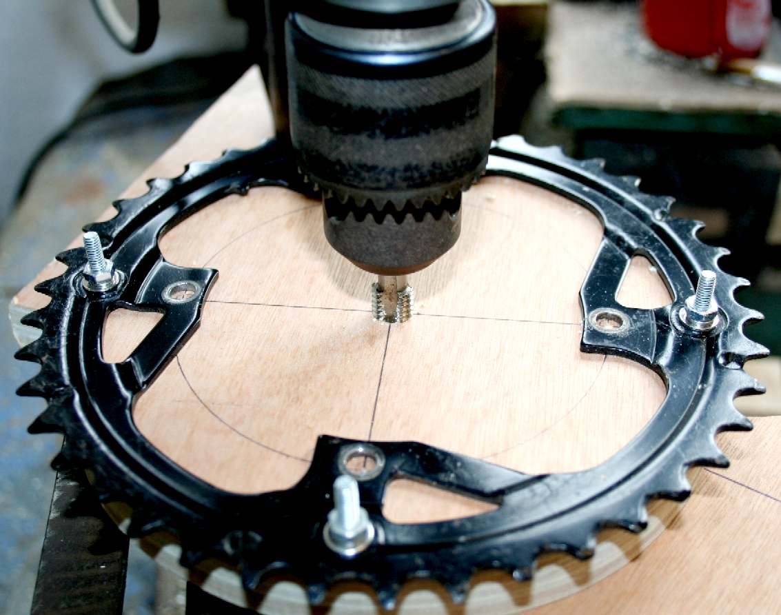
TAPPING A THREAD - Use a lathe or a pillar drill to cut a thread in the plywood, so that the cog is at 90 degrees to the shaft. By threading the shaft through the plywood, rather than simply drilling a 10mm hole, the mechanical integrity is that much better.
DRIVE TRAIN - That is one side completed. We now need crankshafts from the plywood cogs to the end of the leg axles - timed of course, to describe one of the walking cycles at the head of this page. Note that we are using 42 teeth per sprocket for the prototype. Can you tell us why?
Please note that this transmission is Design Copyright and that this photograph is Copyright © Jameson Hunter Ltd 14 February 2016. All rights reserved. You will need permission from Jameson Hunter to be able to reproduce it.
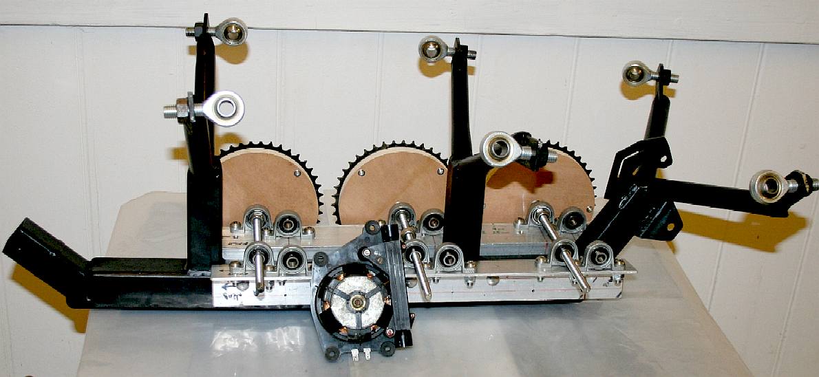
DRIVE TRAIN - The chassis is inverted for adjustments to the transmission. Note the head and tail sections have been removed for these operations. A small pancake motor is shown in front of the chassis.
Please note that this transmission is Design Copyright and that this photograph is Copyright © Jameson Hunter Ltd 19 February 2016. All rights reserved. You will need permission from Jameson Hunter to be able to reproduce it.
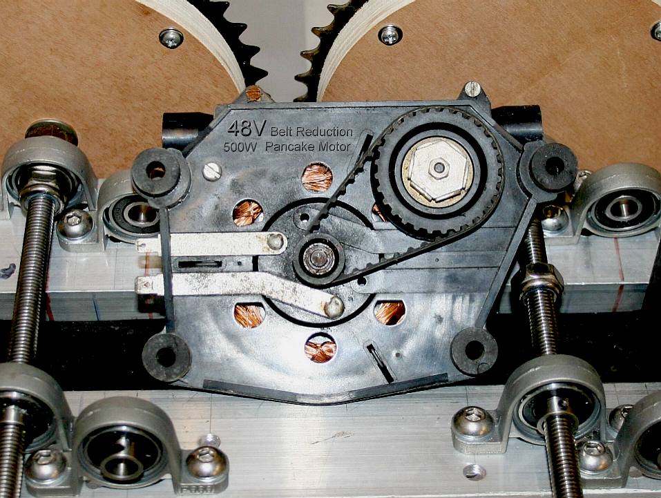
MOTORS - This example is a small pancake design that features a belt drive first stage reduction. The chassis can take six of these rubber mounted units to provide 4 horsepower (3kW) for fairly rapid traction.
Please note that this transmission is Design Copyright and that this photograph is Copyright © Jameson Hunter Ltd 19 February 2016. All rights reserved. You will need permission from Jameson Hunter to be able to reproduce it.
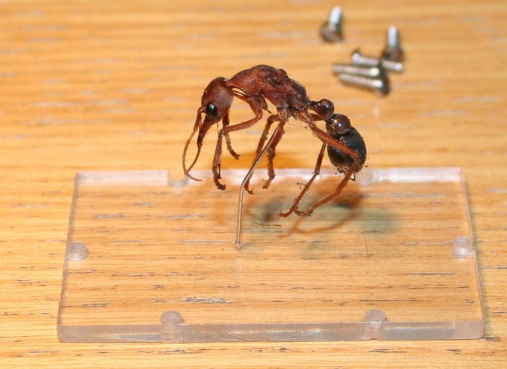
BULLDOG ANT - This is the specimen that we have been loaned to be able to complete this particular feasibility study. It is about 35 years old. It comes from the Australian outback where they are fairly common and feared by all because they can jump many feet in one bound, so can outrun a man for short distances. They also have a nasty sting that can paralyze a man. Phew! That is at 25mm in length. Now imagine the animal 110 times that size. That equals 2.74 meters or 9 feet.
Readers might be interested to note that the above animal killed and ate a tarantula and a scorpion in real life, and for that reason is highly regarded as a fighting machine.
USEFUL FORCE CONVERSION TABLE
LINKS & REFERENCE
battle
Kits Kellycontroller 24v-48v 300a separately excited with regen Myskunkworks 200 amp PWM speed controller Electric scooter parts speed controllers 48 volt Buggies built for fun UK links MIT artificial intelligence laboratory Mind Creators insect locomotion http://www.mindcreators.com/insectlocomotion.htm http://chabin.laurent.free.fr/gaits.htm http://www.csail.mit.edu/ http://www.electricscooterparts.com/speedcontrollers48volt.html http://kellycontroller.com/kdz48303gdv24v-48v300aseparately-excited-with-regen-p-1364.html http://myskunkworks.net/index.php?route=product/product&path=60&product_id=101 http://www.battlekits.com/ http://www.gngebike.com/apps/webstore/products/show/3019663 http://www.electricscooterparts.com/bicyclesprockets.html https://www.aldebaran.com/ http://www.softbank.jp/en/ http://electronics.howstuffworks.com/gadgets/other-gadgets/stun-gun.htm http://lynchmotors.co.uk/ http://www.nestle.co.uk/ http://www.mufg.jp/english/ http://www.maplin.co.uk/ http://www.royalmail.com/ http://www.bostondynamics.com/robot_bigdog.html http://uk.rs-online.com/web/c/automation-control-gear/sensors-transducers/strain-gauge-accessories/ http://zjmy-lu.en.made-in-china.com/product/YKNnjrEkZWVS/China-800W-36V-W-Bracket-Electric-Motor-Kit-W-Control-Box-Throttle-F-Scooter-My1020.html http://www.robots.nu/robot-animals/ http://buggies.builtforfun.co.uk/Links/index.php http://www.maxonmotor.com/maxon/view/application/STICK-INSECT-ROBOT-AB http://www.knbefxgroup.com/
Tel:
01524 38 33 44 http://www.jandsfasteners.co.uk/
LEFT - Movie idea, lurking beneath the Antarctic ice is a discovery that scientists will die for. This story is now the subject of a low budget trailer to be produced mostly in the UK. The promoters are looking for backers. The UK will contribute 20% toward production costs. Roughly 60% of a low budget film may be pre-sold as distribution rights, leaving 20% finance to source. The deal is that investors recover 120% on their project stake within 12 months of shooting, with an income stream thereafter from networks and merchandising. Producers and directors please take note that there is a significant audience for well made movies of this genre. Look at what happened when they remade Godzilla. RIGHT - 2015 Movie poster for Ant-Man, an adaptation from the Marvel graphic novel.
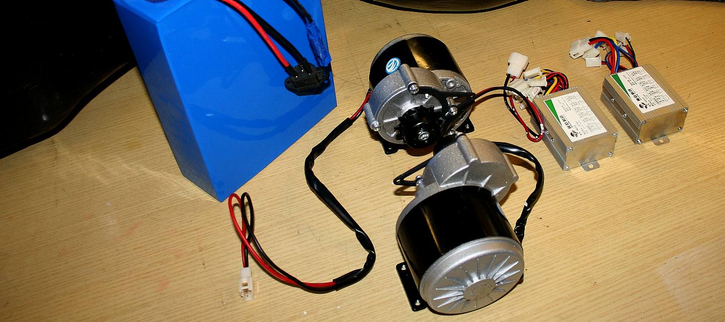
DRIVEN - Here we see a 48 volt 2kW hour lithium battery pack, two 500 watt motors with gear reduction and two 500w electronic speed controllers.
A Sectasaur™ (thawed) - now on permanent display at Herstmonceux Museum, in Sussex, England.
ANTICS - ARDUINO - ARMOUR - ARTWORK - BIOLOGY - BLACK BOX - COMPUTERS - ELECTRONICS - ENERGY - FRAME - HEAD - JAWS - JIMMY WATSON - KITS - LEGS - MECHANICS - MOTORS - MOVIE - PHOTOGRAPHY - -ROBOTICS - R/C DRONE - SENTRY - SOFTWARE - SOUND PROOFING - SPEED - SUSPENSION - TAIL - WEAPONS - WARGAMING
DINOSAURS - DOLPHINS - HUMANOIDS - RAYS - SHARKS - WHALES
|
||||||||||||||||||||||||||||||||||||||||||||||||||||||||||||||||||||||||||||||||||||||||||||||||||||||||||||||||||||||
|
This website is Copyright © 2024 Bluebird Marine Systems. The names Bluebird™, Bluefish™, Miss Ocean™, SeaNet™, SeaVax™ are trademarks. All other trademarks are hereby acknowledged. The design of the Robot Ant on this page is design copyright © December 15 2015, all rights reserved - Jameson Hunter Ltd. IMPORTANT NOTE: Under no circumstances may our products, or those of Jameson Hunter Ltd, be used by any military or law enforcement organization, for any warlike, combat, or peacekeeping crowd control purposes. Anyone purchasing one of these units will be required to sign a binding undertaking (Deed) to that effect. Any unit found to have been purchased by proxy, will be confiscated, along with civil remedy in respect of breach of contract, that all parties in the chain will be vicariously liable for - to include damages for vehicles developed from our designs without our consent - and possible fraud issue from the deception. In addition to copyright theft, the law of passing-off applies.
|
||||||||||||||||||||||||||||||||||||||||||||||||||||||||||||||||||||||||||||||||||||||||||||||||||||||||||||||||||||||