|
The mbed
micro computer pinout board
MBED COMPUTER
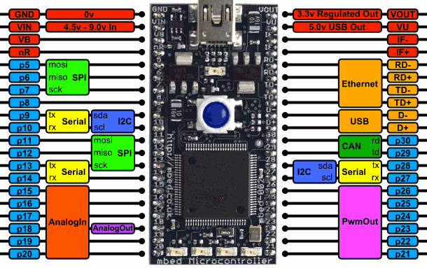
The mbed Microcontrollers are a series of ARM microcontroller development boards designed for rapid prototyping.
The mbed NXP LPC1768 Microcontroller in particular is designed for prototyping all sorts of devices, especially those including Ethernet, USB, and the flexibility of lots of peripheral interfaces and FLASH memory. It is packaged as a small DIP form-factor for prototyping with through-hole PCBs, stripboard and breadboard, and includes a built-in USB FLASH programmer.
It is based on the NXP LPC1768, with a 32-bit ARM Cortex-M3 core running at 96MHz. It includes 512KB FLASH, 32KB RAM and lots of interfaces including built-in Ethernet, USB Host and Device, CAN, SPI, I2C, ADC, DAC, PWM and other I/O interfaces. The pinout above shows the commonly used interfaces and their locations. Note that all the numbered pins (p5-p30) can also be used as DigitalIn and DigitalOut interfaces.
The mbed Microcontrollers provide experienced embedded developers a powerful and productive platform for building proof-of-concepts. For developers new to 32-bit microcontrollers, mbed provides an accessible prototyping solution to get projects built with the backing of libraries, resources and support shared in the mbed community.
FEATURES
NXP LPC1768 MCU
High performance ARM® Cortex™-M3 Core
96MHz, 32KB RAM, 512KB FLASH
Ethernet, USB Host/Device, 2xSPI, 2xI2C, 3xUART, CAN, 6xPWM, 6xADC, GPIO
Prototyping form-factor
40-pin 0.1" pitch DIP package, 54x26mm
5V USB or 4.5-9V supply
Built-in USB drag 'n' drop FLASH programmer
mbed.org Developer Website
Lightweight Online Compiler
High level C/C++ SDK
Cookbook of published libraries and projects
The mbed NXP LPC1768 is one of a range of mbed Microcontrollers packaged as a small 40-pin DIP, 0.1-inch pitch form-factor making it convenient for prototyping with solderless breadboard, stripboard, and through-hole PCBs. It includes a built-in USB programming interface that is as simple as using a USB Flash Drive. Plug it in, drop on an ARM program binary, and its up and running! It is our most full featured board and is great for all kinds of general prototyping. If you're not sure which mbed to get, this is your best choice. 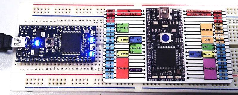
MBED HDK
The mbed Hardware Development Kit (HDK) provides full microcontroller sub-system design files and firmware for building development boards and custom products that benefit from the native support of the mbed SDK and free mbed Online Compiler and mbed Developer Platform.
The mbed HDK specifies all support components and circuits including the CMSIS-DAP Interface design that provides simple USB drag-n-drop programming and CMSIS-DAP debug interface for the target microcontroller.
Development boards that are already based on the mbed HDK are the quickest way to get started with the mbed platform. We manufacture official mbed Microcontroller modules that are specifically optimised for flexible rapid prototyping, and are available from distributors worldwide. Our partners are now also creating mbed-enabled hardware such as ultra low-cost ARM evaluation boards in the popular Arduino form-factor.
MICROCONTROLLER
SUB SYSTEMS
Each of the subsystems designs include
* Hardware design schematics (Eagle format)
* Interface binary for the CMSIS-DAP interface
CMSIS-DAP INTERFACE
The CMSIS-DAP Interface is a microcontroller based single chip solution that provides, Drag and Drop programming, CMSIS-DAP debugger and USB serial interface to a range of Cortex-M based microcontrollers.
The small footprint, low number of passive components and rich feature set provide a low cost, low overhead solution that can easily be integrated on a
PCB.
The firmware required to turn the low cost microcontroller into a powerful programming, debug and communication interface, is included witht eh HDK and can be used freely, including for use in commercial products.
The CMSIS-DAP interface provides three main functions over a single physical USB connection :
* USB Disk “drag and drop” programming - ideal for fast turn around prototyping, or in-field upgradable products
* Debug interface using the CMSIS-DAP - Provides full debug capability with tools like Keil MDK
* USB Serial interface between the host computer and the target
BENEFITS OF THE HDK
There are various benefits to building a custom design onto of the mbed HDK. The ready made schematics are a great short cut, so you can get started on all the things that make your design, without worrying if you've correctly implemented all the "necessary bits" of the design. The mbed HDK incorporates the CMSIS-DAP interface. This provides USB drag and drop programming, CMSIS-DAP debugging and USB serial communication. The mbed SDK supports each of the exact configurations of HDK designs, and libraries that have been written to the APIs in the mbed SDK are highly reusable. Lastly, the mbed community has developed a wealth of libraries, applications and code examples using the SDK/HDK, and this active community offers a lot of opportunities for support and even hiring in required skills.
USING THE MBDE HDK IN CUSTOM DESIGNS
The mbed HDK currently supports
* LPC812M10
* LPC1768
* LPC11U24 (This "lite" version uses LPC11U24 on chip bootloader, no CMSIS-DAP interface required)
DOWNLOAD - The mbed HDK can be downloaded from the repository.
Jon's
autonomous Savage truck conversion JON'S
SPARKFUN AVC - GOOD EXAMPLE ROBOT PROJECT ABOUT
JON Jon
started this project with an Arduino microcontroller and autonomous vehicle pcb.
Jon says that ever since the SparkFun AVC event started a few years ago, he's wanted to enter. But
that living in the UK made it difficult to justify the expense of flying to Colorado.
Purely coincidentally he was in the US for a conference the week before a
competition, so as the opportunity presented itself he entered himself for the
2013 competition. Jon
is passionate about electronics/robotics and wishes he had more time to indulge
the hobby. But he has a demanding IT job for a large global digital agency.
His dad was an engineer and Jon had a ZX81 when he was 11 as a jump start to an
interest in electronics. He then studied at Southampton University in the late 80′s.
Jon built robots for various school and university projects and would have liked
to work in robotics, but it's just a hobby now. He currently has a collection of home built and bought robots, including: *
A 3Pi *
A scratch build two wheel balancing robot, *
An antique 6DoF hydraulic arm and, *
A RoboNova biped. Jon
is very much into Arduino, Raspberry Pi and mBed and other projects based around AVR
microcontrollers. He also has a fascination for lasers, having built a number of laser
projectors. VEHICLE
BASE UNIT
Tough is good, but controllable is better. Jon chose an HPi Savage Flux XS radio controlled car
(apparently the “world’s fastest mini monster truck”) for his contact with
terra-firma. This is a 55 mph truck, presumably governed, but maybe just
tempered a little, as in don't pull the trigger too hard. 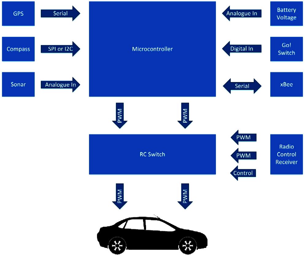
How
it all comes together - the simple version THE
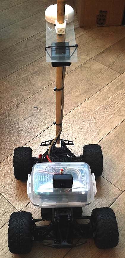
BRAINS The brain
of the Savage is an mBed (ARM base microcontroller) attached is a high accuracy GPS
(about 1.5-2m accuracy using SBAS), an electronic compass and ultrasound range finder,
mounted high on a wooden mast. Jon's
Savage has a GPS receiver to provide its current position, and a magnetometer to provide its current heading. A microcontroller controls the speed and steering servos and
he can switch between autonomous control and manual control using the third
channel of the radio set. The course has obstacles, so
some basic obstacle avoidance is included. Jon used a small sonar to provide the distance to obstacles directly in front.
The mBed ingests the GPS data, range finder and compass data and works out where it’s currently pointing and the delta to where it needs to point to reach the next waypoint. The delta is fed in to a PID control algorithm that controls the steering servo.
The speed controller
will be proportional to the distance from the next waypoint such that the truck
slows as it nears a turn point. The range finder is processed and inserts an offset in to the PID control input if it detects an obstacle, to try and steer round it. THE
COMPETITION The AVC on paper sounds simple;
build an autonomous vehicle that can navigate an obstacle course without human intervention.
DARPA held a similar competition that took several events before a car finally
completed the course across a desert. Wisely,
Jon decided to enter the ground competition, as the aerial challenge
is way more complex. By wya of a shortcut he decided to base his robot on a radio controller car chassis.
He already had an HPi Racing Savage Flux XS, a 4×4 mini monster truck that’s fast and simple.
It has just two controls, steering and speed. As a bonus, the radio comes with three channels, so
he could use the 3rd channel as a control to switch between radio control and autonomous control, and quickly switch back to radio control during testing
if something drastic went wrong. SparkFun provide the course details with all the GPS coordinates. The course is roughly rectangular with four sides, a start finish straight, a side with 4 barrels as obstacles, a side with a hoop to go under for bonus points and a side with a small ramp to
jump; again for bonus points. The course is about 200 feet square, with the course being about 20 feet wide. With basic GPS accuracy of 2-4m this made the challenge perfectly achievable
- just. FEEDBACK Jon
needed a way to monitor and debug the car during testing. So he decided to add an xBee
to get basic debug information from the car in real time visible via a simple PC desktop app to display
information in a user friendly way. 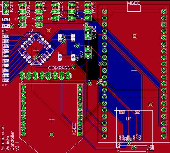
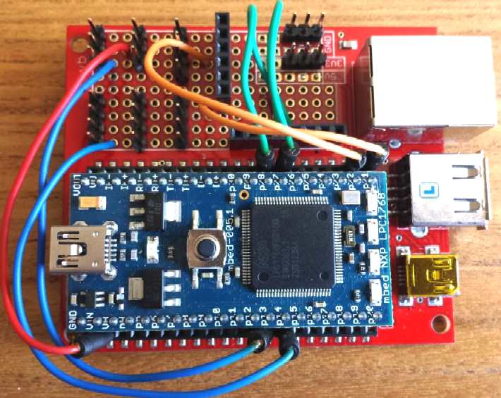
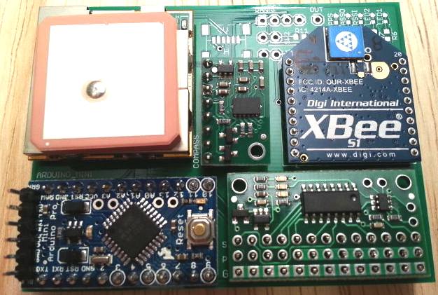
Jon's
mbed prototype development boards PHASE
1 DEVELOPMENT
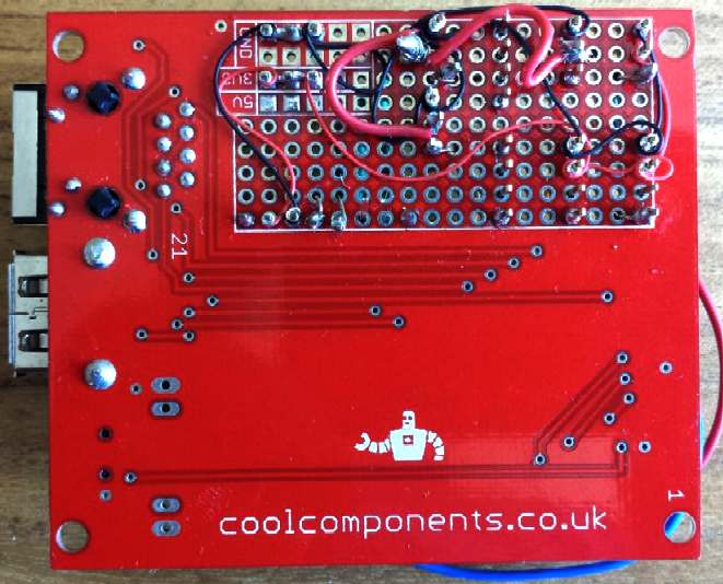
Jon made use of components he already had, including an EM-406A GPS module and a Pololu 3D magnetometer breakout board.
He bought a MaxSonar sonar from CoolComponents and an RC switch from Pololu to give
him that failsafe control, switching to (drone) radio control.
The initial plan was to use an Arduino, as he had lots of them and bags of experience programming them.
Jon likes old school wire wrap for prototyping, so he prototyped a basic Arduino shield to tie the 3 sensors together.
The initial testing went well using a third party GPS library and magnetometer library to ingest the data,
which gave a basic heading to a GPS waypoint, and a bearing from the magnetometer on the bench. The PWM output worked controlling two test
servos. Armed with this he confidently sketched a custom PCB to shrink the design
to fit in/on the Savage, when garden testing could begin. The custom board specification
was sent out to be made.
Once the custom PCB arrived Jon had the basic software running. The premise of the control system is to navigate to waypoints,
much like the skipper of a ship, so the GPS coordinates are used to calculate a bearing from the current position to the next way point. This is the heading the car needs to steer. However, the car is on rough terrain and will never steer in a straight line. The course the car is taking is provided by the magnetometer, which gives
a bearing based on the direction the car is pointing in. To reach the waypoint
without wasted effort, the difference between the car’s heading and the GPS bearing needs to be kept as close to zero. One of the best ways of doing this is to use a PID controller.
Jon had a basic control loop written, for the Arduino, which looks something like this pseudo code:
While(CurrentWaypoint < TotalWaypoints) {
MagneticHeading = GetMagnetometerHeading();
GPSLocation = GetGPSLocation();
GPSHeading = GetGPSHeadingToWayPoint(GPSLocation,WayPoint);
PID_input = MagneticHeading – GPSHeading;
ComputePID();
SetSteering(PID_output);
If (DistanceToWaypoint < 2m) then CurrentWaypoint++;
} |
This should steer the car in a straight line from wherever it is, to a defined GPS waypoint. Once it gets within 2m of the way point, it
would then move on to the next waypoint. Once all the waypoints have been reached,
the mission (program) terminates. At least that was the plan.
AVC SWITCH - ARDUINO TO MBED
But, as with the best laid plans, once the initial Arduino prototype was built
Jon started having problems with the board. He rigged it on a workbench with two servos attached directly to the speed and steering outputs. The code kept crashing and the board would
hang - typically in strange ways. Jon would comment out lines of code, and it would be more stable, then
he’d put different code in and it would crash again. It seemed to have little to do with the content of the code, and more to do with the *amount* of
code.
Jon had experienced this problem with his balance bot. The code randomly crashed there too and if you run some basic compiler tools on the code, the code is very close to the RAM limit of the microcontroller.
Not good. The tools were not up to the task.
Jon had been looking at mBed for a while and bought a board to experiment with and this seemed like
the perfect project to take the plunge and learn mBed on. He had toyed with a
switch to an Arduino Mega, which is what he did on my Balance Bot, but the Mega is physically so much larger, and
he wanted to fit the resulting controller inside the Savage vehicle. So he bit the bullet and scrapped everything
he’d done to date. Jon says there’s nothing better than a looming deadline and nothing
working to focus the mind on learning a new platform.
Jon had an LPC1768 mBed which had much better specs. He would classify its advantages over Arduino as: 1.
Faster – 100 MHz vs. 16 MHz. Six times more instructions per second means more power.
He could read the GPS and magnetometer at a much faster frequency and baud giving
better accuracy and control.
2. More hardware serial ports – 1 UART on the Arduino vs. 3 UARTs on the mBed –
Jon needed a fast serial port for the GPS and one for debugging via xBee.
3. More RAM (32 KB vs. 2KB on the Arduino) more than enough to run all the various libraries and calculations without crashing.
4. Hardware floating point – This is important for GPS as the LAT/LON coordinates are all floating point numbers. There would be lots of complex trigonometry with floating point numbers happening every second. Hardware floating point would be a huge improvement in performance.
5. The last benefit was unexpected. The mBed has an RTOS library that allows you to run multiple independent threads. This made the code design much simpler. Rather than having one big main loop, that has to do everything,
you can split up the tasks in the threads. E.g. one just ingesting and parsing GPS NEMA data, one outputting debug information, one running the PID control loop, etc.
Heaven.
The design changed from Arduino to mBed overnight and
Jon planned out a new board. Although, this is explained on Jon's blog in a
couple of pages, it took about 6 weeks in elapsed time to figure out. Lots of late night debugging, scratching
of heads, reading on the interweb and chatting to people on forums.
Jon designed another PCB for the mBed solution and using the cheap PCB outsource
fabs, he calculated it would arrive a couple of weeks before the competition. He
had no choice but to commit to the new design. There would be no time to reinvent the solution a third time.
Jon says that if it hadn’t gone well, he would have been soldering on the
plane. PCB's
Jon is quick to point out why he likes having custom PCBs, instead of wire wrap or breadboards.
Well, we'd all agree on that we expect for different reasons. Jon says that he
jumps to custom PCB very quickly in
his prototyping phase and he explains that simply as increased reliability. In the past
he would have run projects from a breadboard. But he'd drop the project, or
after traveling somewhere in a box, suddenly two of the wires would have popped out of the bread board.
And that would waste hours tracing every connection to work out where they went and which ones have popped out. Plus with moving robots, the
constant bouncing tends to give boards a good workout unless they are well and
truly bolted down, also making wires come lose. Custom
PCBs are now very cheap and easy to make (once you’ve used Eagle a few times) and they make the circuit an order of magnitude more reliable,
smaller and neater. In addition they are then easy to change with a spare if something
happens, or you can cut a trace and solder in a jumper wire. Plus things like xBee, which has 2mm pitch legs, aren’t breadboard friendly, so you end up with breakout boards, again that come lose. Custom PCBs
solve all of these problems and save time in the long run. 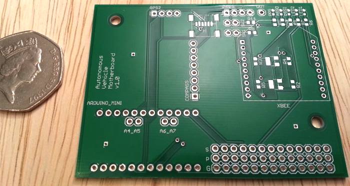
Jon's
final ASV PCB PHASE
2 DEVELOPMENT
Once more on the starting blocks, Jon
ported the existing Arduino GPS and magnetometer libraries to mBed, which meant the bulk of
his code would just migrate to the new platform. Jon says that the mBed platform
"is fantastic. Its proper C++, not the cut down libraries of Arduino."
he got things like printf back, which are huge resource hogs on Arduino. There were other benefits too. There is a simple SD Card library, so
Jon could store his waypoints on an SD card, which would mean that when making small edits during
a competition, it wouldn’t mean that he needed to recompile the code and upload it to the mBed.
He could just edit the text file in an editor and re-read them. Bonza!
Jon structured his code slightly differently to make use of the multithreading benefits of mBed too.
He had three threads: 1.
The first was dedicated to just ingesting the GPS NEMA strings and converting them in to numbers that were stored in a global variable structure.
He ran the GPS at 4 Hz to give good accuracy.
2. The second thread was dedicated to providing debug data. It ran every second, (or every 2 seconds) and dumped all the current readings of all the sensors and internal variables over the xBee. These would then be read by the desktop app and displayed in a user friendly way.
3. The final thread was the main loop. This ran the PID control and used the data from the GPS structure and magnetometer to feed the PID, and then set the steering servo with the output of the PID.
As
with Phase 1., Jon got the prototype working on an mBed development board while
he waited for the custom PCB to arrive. He used wire wrap with some jumper leads to plug in to the mBed. The prototype worked OK and
he started to get a basic system working. It was not long before a change to the
custom board. FINALLY
- The entry for the Autonomous Vehicle Competition in the US was built and even (partially) tested.
The Autonomous Vehicle Competition is run by SparkFun Electronics, held in Boulder, Colorado. http://avc.sparkfun.com
& http://www.sparkfun.com
Mbed
autonomous vehicle with manual RC (drone mode) override - the full system working on the bench for the first time. You can see the third channel switch the control between RC and
mBed. During mBed control, the compass on the mBed controls the steering servo, and the wheels track the position of the compass. During RC control, the transmitter has control and the mBed does nothing
ARDUINO
- ARM
HOLDINGS - BEAGLEBOARD
- MBED
- PICAXE
- RASPBERRY
PI
LINKS
Atmel -
Produce ICs, the AVR 8 bit micro controllers powering the Arduino development
boards.
SparkFun -
US based electronics components supplier. Tons of development boards, widgets
& tutorials.
AVRFreaks -
Discussion Forum dedicated to the AVR family of microcontollers. Very helpful
& friendly community.
Pololu
– Pololu Robotics and Electronics, full of robot kits, robot parts and robot
electronics.
CH
Robotics – Inertial and Orientation Sensors.
DIY
Drones – A complete community for building autonomous vehicles, hardware,
software, forums and more.
Ponoko
– 3D printing, plastics, ceramics and S. Steel. Laser cutting - including: acrylic
leather, wood, card.
http://blog.mostlyrobots.net/tag/autonomous-vehicle/
http://beagleboard.org/project/AUV/
http://beagleboard.org/project/openrov/
http://beagleboard.org/project/Motion+Control/
http://beagleboard.org
http://beagleboard.org/Products/BeagleBone%20Black
http://www.logicsupply.com/products/bb_bblk_000
http://www.logicsupply.com/categories/motherboards/arm
http://www.gotransat.com/tracking/
http://www.picaxe.com/What-is-PICAXE/
http://3drobotics.com/
http://wiring.org.co/
http://www.arduino.cc/
http://www.designboom.com/technology/arduino-factory-tour/
http://www.raspberrypi.org/
http://www.python.org/
http://www.youtube.com/user/RaspberryPiTutorials
http://fishpi.org/contact.html
http://fishpi.org/forum/
http://rockblock.rock7mobile.com/
http://www.oceanbusiness.com/
https://code.google.com/p/raspy-juice/
http://www.yellowbrick-tracking.com/
http://fishpi.org/wiki/index.php?title=The_Proof-Of-Concept_Vehicle
http://fishpi.org/wiki/index.php?title=The_Prototype
http://fishpi.org/wiki/index.php?title=Hull_Design
http://www.modelsbydesign.co.uk/
http://www.raspberrypi.org/
http://international.findmespot.com/
http://www.amsat.org/
http://en.wikipedia.org/wiki/Composite_material#Autoclave_moulding
http://www.enecomitalia.com/ENG/caravans.html
Arduino
http://en.wikipedia.org/wiki/RobotC
|