|

Anton
Flettner - Inventor
HISTORY
OF FLETTNER ROTORS
A rotor ship, or Flettner ship, is a ship designed to use the Magnus effect for propulsion. To take advantage of this effect, it uses rotorsails which are powered by an engine. The Magnus effect is a force acting on a spinning body in a moving airstream, which acts perpendicularly to the direction of the airstream. German engineer Anton Flettner was the first to build a ship which attempted to tap this force for propulsion.
Flettner's spinning bodies were vertical cylinders; the basic idea was to use the Magnus effect. The idea worked, but the propulsion force generated was less than the motor would have generated if it had been connected to a standard marine propeller. These types of propulsion cylinders are now commonly called Flettner rotors.
His first idea was to produce the propulsion force by using a belt running round two cylinders. Later Flettner decided that the cylinders would be better rotated by individual motors. Flettner applied for a German patent for the rotor ship on 16 September 1922.
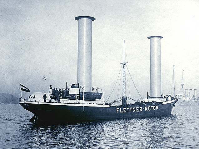
Assisted by Albert Betz, Jacob Ackeret and Ludwig Prandtl, Flettner constructed an experimental rotor vessel, and in October 1924 the Germaniawerft finished construction of a large two-rotor ship named Buckau. The vessel was a refitted schooner which carried two cylinders (or rotors) about 15 metres (50 ft) high, and 3 metres (10 ft) in diameter, driven by an electric propulsion system of 50 hp (37 kW) power. In 1926, a larger ship with three rotors, the Barbara, was built by the shipyard A.G. Weser in Bremen.
TRIALS
Following completion of its trials, the Buckau set out on her first voyage in February 1925, from Danzig to Scotland across the
North Sea. The rotors did not give the slightest cause for concern in even the stormiest weather, and the rotor ship could tack (sail into the wind) at 20-30 degrees, while the vessel with its original sail rig could not tack closer than 45 degrees to the wind.
On 31 March 1926, the Buckau, now renamed Baden Baden after the German spa town, sailed to New York via South America, arriving in New York harbor on 9 May.
It was found at the time that the rotor system could not compete economically with the
diesel engines that were also being developed for ships in this era. Flettner turned his attention to other projects and the rotors were dismantled. Baden Baden was destroyed in a Caribbean storm in 1931. Due to the rising cost of
fossil fuels, as well as environmental concerns, there has been renewed interest in the concept in the later 20th century, starting with Jacques-Yves Cousteau's Alcyone in 1983.
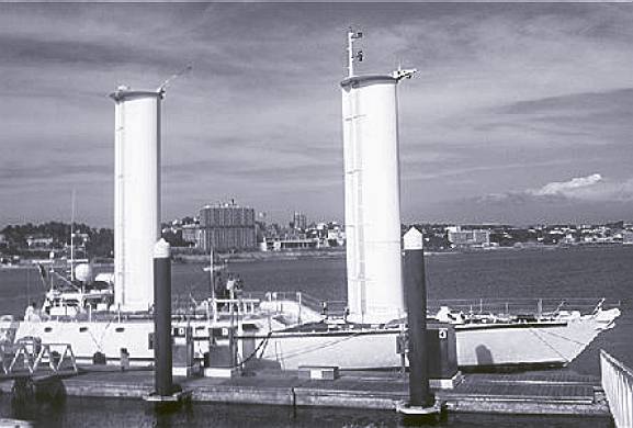
Jacques-Yves
Cousteau built the Alcyclone above in 1983 to test his concept, which is
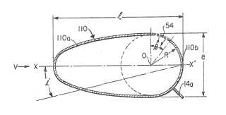
part wing-sail with a form derived from that associated with the Magnus
effect (right). The drawing below (left) was filed as part of patent
number US
4630997
The University of Flensburg is developing the Flensburg catamaran or Uni-cat Flensburg, a rotor-driven catamaran.
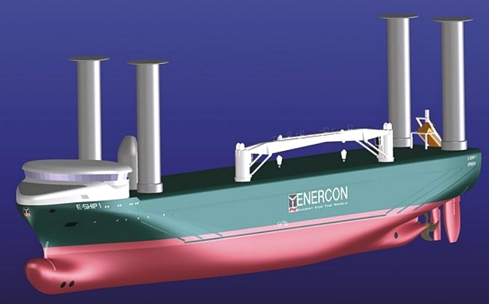
The German wind-turbine manufacturer Enercon launched and christened its new rotor-ship E-Ship 1 on 2 August 2008. The ship will be used to transport turbines and other equipment to locations around the world. The maiden delivery of turbines for Castledockrell Windfarm arrived in Dublin Port on 11th Aug 2010.
In 2009 the Finland-based maritime engineering company Wärtsilä unveiled a concept for a
cruise-ferry that would utilise flettner rotors as means of reducing fuel consumption. This concept has been linked with the Finnish ferry operator
Viking
Line, who have stated they will make a decision on whether or not they'll order new ships during 2010.
Stephen H. Salter and John Latham recently proposed the building of 1,500 robotic rotor-ships to mitigate
global warming. The ships would spray seawater into the air to enhance cloud reflectivity. A prototype rotor ship was tested on Discovery Project Earth. The rotors were made of carbon fibre and were attached to a retrofitted trimaran and successfully propelled the vessel stably through the water at a speed of six knots. The focus of the experiment was based on the ability for the boat to move emissions free for a specialized purpose leaving it unclear whether or not the efficiency of the rotors was on parity, inferior to, or superior to conventionally propelled vessels.
MONOROTOR
SYSTEM
Recent decades have brought a host of
green ship technologies such as less resistant hull shapes and coatings, more efficient engines and propellers, waste heat recovery and many others, altogether resulting in substantial fuel savings and carbon emission mitigation. However, mainly aimed at new builds, most of the innovations cannot be implemented cost effectively to existing vessels. So, for the majority of the about 40,000 merchant ships around today, slow steaming remains the main route towards meaningful fuel savings. In any case, when all is said and done a vessel relying only on its engine for propulsion still needs to burn substantial amounts of
fossil fuel to move cargo on the high seas. At this point the only way to further savings and emission mitigation remains the harvesting of renewable energy.
To that effect the last twenty years has seen many efforts towards reviving wind power as a means of propulsion for merchant vessels. Notably, the “Dynaship” and the Japanese “UT Wind Challenger”, solid-sail full rigger concepts, the “SkySail” kite sail system, and the Enercon E-ship Flettner rotor vessel. Also, many new ship designs include arrays of PV solar panels.
The jury is still out on contemporary sailing concepts, but beyond any doubt some will be utilized in cargo ships within the next few years. Many marine engineers agree that Flettner rotors represent the closest approach to a safe, push-button operated sailing system. It is a well -known, proven technology, which can readily be implemented in new builds. However, current concepts require several, deck-mounted rotors in order to obtain meaningful fuel savings, are expensive to install, and tend to impede loading and unloading and daily operation of the vessel
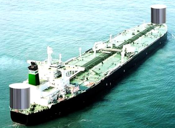
The Monorotor® (patents
pending) is a self-contained wind propulsion system, specially designed for easy retrofit onto existing bulk carriers and tankers. The term Monorotor signifies a single rotor, which is able to match the performance of the multiple slim rotors historically used and currently being proposed for cargo vessels. To accomplish this it needs to have a large diameter, typically 8 to 20 meters, and a height of 20-25 meters. With these dimensions the rotor system would be a significant obstacle if placed amidships on the main deck, besides obstructing the view from the bridge. As a consequence they are located at the forepeak above the forecastle, or aft of the superstructure, straddling the stern. Due to the distance from the helm to the forepeak, on most vessels the blind sector represented by the Monorotor, as viewed from the bridge, will be within the maximum 5 degrees specified by the IACS.
The main objective behind the Monorotor concept is to provide a modular, self-contained system which can be easily customized to fit a wide variety of cargo vessels.
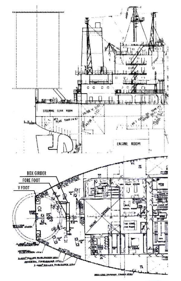
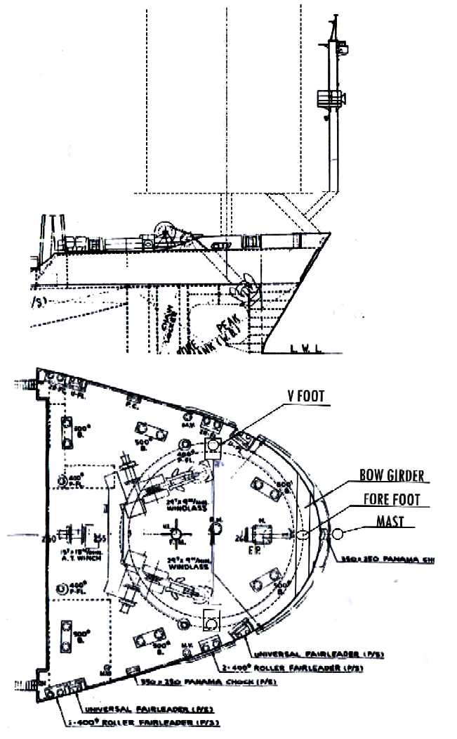
Even though Monorotors can be used individually, a common installation will comprise two modules, with one rotor on the forepeak above the forecastle deck and another straddling the stern, elevated above the aft deck. The typical support bases are tripods comprising two rear legs which are angled symmetrically outward, and one foreleg pointing forward at an angle of about 45 degrees. The legs are tubular steel fabrications, 0.5 to 1 meter in diameter, supported on heavy footplates which connect with hull strong points or wide box girders for distributing the weight load and working forces over a large area of deck and underlying hull frames. The top of each leg is exactly contoured and welded onto the tubular casing of the drive shaft assembly, thus defining the top of the rigid pyramid-shape base structure.
The accompanying drawings serve to illustrate how the Monorotor support bases may be customized in order to minimize the need for modifications to the vessel receiving the retrofit. Another objective is to avoid re-locating essential equipment like bollards and anchor- and mooring-windlasses.
Monorotors will be made available in several models with diameters ranging from 8 to 24 meters featuring one of three standard driveshaft assemblies. The “Configurable Specification” table lists variables, which may be customized to comply with client requests.
Flexibility of design is accomplished by means of changes to the support legs such as their length, attachment angle, diameter, wall thickness and the way they are welded onto the driveshaft assembly, foot plates and box girders.
* Rotor clearance, typically 3-4 meters may be increased when required.
* The Offset distance from the rotor axis to the forefoot, in order to keep clear of deck equipment. The rotor axis may be cantilevered out from the stern if necessary in the case of a short aft deck.
* The Spread, as wide as possible while keeping clear of bollards and cable guides.
* Box girders, optional, may mitigate the need for internal reinforcements.
* Mast support base: Bow rotor option.
MAIN CHARACTERISTICS OF MONOROTOR WP FOR CARGO SHIPS
Each rotor generates the same amount of thrust as 2-4 slim rotors of similar height.
Is less complex with few moving parts.
The supporting structure may be designed more efficiently within the ample space inside the rotor. Less reinforcement of the vessel structure is required since forces may be spread over a larger area. The main support legs, which connect with hull plating or wide-base deck support structures may be placed 10+ meters apart, only taking up a small amount of deck space.
Rotors are located at the extreme stern and bow, well clear of hatches, cranes and anchoring and mooring equipment. Interference with gear and daily operations is minimized because Monorotors are elevated 3-4 meters above deck, also raising crew safety.
A free fall lifeboat may be located and launched under the shelter of the aft Monorotor.
In most cases few modifications are required. During installation the one-piece drive and support module is lifted on board first and welded in place, and then the rotor is added and bolted on to the drive shaft top flange. Only two lifts are required. The entire process including power and control cabling can be performed within a week, possibly combined with scheduled maintenance.
The Monorotor drive shaft is supported by two large capacity roller bearings. They are oil lubricated and oversized to provide decades of lift. The 1 -2 ton gear motor is backed by a 5 year warranty. In the unlikely event of a bearing- or drive failure the vessel may proceed as normal under engine power until repairs can be performed.
Maximum rotation speed is low 40-80 RPM depending on diameter.
Operating parameters are vessel course and speed, wind direction and velocity, rotor RPM and generated thrust. The variables are monitored and the system is operated automatically by a microprocessor control module located in the wheelhouse. No specialized crew is required.
CALCULATED PERFORMANCE FROM A 16 METER x 22 METER TALL MR
|
Suited for a 30,000 to 40,000 dwt Bulk Carrier or Tanker.
Cruise speed: 14 knots
|
Wind speed m/s
|
5
|
10
|
15
|
20
|
25
|
30
|
60
|
|
Knots
|
9.7
|
19.4
|
29.1
|
38.9
|
48.6
|
58.3
|
116
|
|
Rotor RPM
|
30
|
60
|
60
|
60
|
50
|
43
|
|
|
Thrust tons
|
6
|
24
|
40
|
51
|
52
|
51
|
|
|
Power KW
|
430
|
1700
|
2900
|
3700
|
3700
|
3650
|
|
|
HP
|
585
|
2300
|
3900
|
5000
|
5000
|
4900
|
|
About 50 KW of electric power is required to spin the
Monorotor.
Effect
of
Wind
Direction
|
Wind Angle (degrees)
|
30
|
45
|
60
|
75
|
90
|
105
|
120
|
135
|
150
|
175
|
|
Power %
|
10
|
35
|
59
|
77
|
91
|
99
|
100
|
94
|
82
|
|
|
The rotor is designed to rotate at maximum of 60 RPM. The table above shows how the thrust can be kept within the 55 ton design limit by adjusting the rotor RPM. Thrust is monitored by strain gauges located on the central support at the point of maximum stress. A PLC program continuously adjusts and maintains the Monorotor RPM within safe limits while maximizing thrust. The program also monitors wind speed and angle of roll in order to stop and park the rotor in extreme weather. No specialized crew is required to operate the system.
When evaluating the performance of the rotor system it is important to keep in mind that it contributes thrust and propulsion horsepower. On the other hand, when calculating propulsion horsepower of a marine engine, its rated power must be adjusted for propeller efficiency (0.65-0.70). For example: 2,000 Monorotor horsepower equals about 2,900 engine brake horsepower.
Many owners are looking at solar collectors to supplement the electric power on board. However, dependent on the trade, panels tend to dirty up and often suffer damage due to weather and crew activities.
The top surface of Monorotors, located high above decks and holds is an ideal platform for solar power generation. P/V solar panels installed flat on the 18 meter diameter top surface of a model 16/22 Monorotor may contribute 20-25 kW during daylight hours. The DC power is routed down through the rotor center and on to a DC/AC inverter via a brush and slip ring assembly. Offered as an option under the patent pending Monorotor system.
Aspect Ratio: (Rotor height/diameter)
Experiments indicate that when comparing the thrust of two Flettner rotors of different heights but with the same projected area and rotating at the same spin ratio, the efficiency of the taller and slimmer rotor is higher than that of the shorter and stubbier rotor.
The difference in output is caused by boundary losses due to air flowing from the high pressure to the low pressure zones over the ends of the cylinder. The end areas of the shorter cylinder represent a relatively larger part of the total projected area, causing higher losses and lowering its efficiency. The short circuit of the air stream near the ends can be mitigated by adding larger diameter discs (Boundary effect fences) at the cylinder ends.
Conversely, since the pressure gradients and conditions near the ends of equally tall rotors are the same at similar surface velocities and wind conditions, the efficiency remains the same as well, irrespective of the diameter and aspect ratio.
The Barkley Phenomenon
This interesting characteristic of Flettner rotors is their ability to become “invisible” in strong winds. The effect manifests itself as a distinct drop in drag as the surface to flow velocity is approaching 1. This means that the braking effect of the rotors on a vessel traveling against the wind can be mitigated or drastically reduced by lowering the spin ratio (3-4 to generate thrust) to match the combined velocity of the wind and the speed of the vessel. Besides improving the general efficiency of non- collapsible rotors the Barkley effect can also be utilized to improve the safety of the vessel in inclement weather conditions.
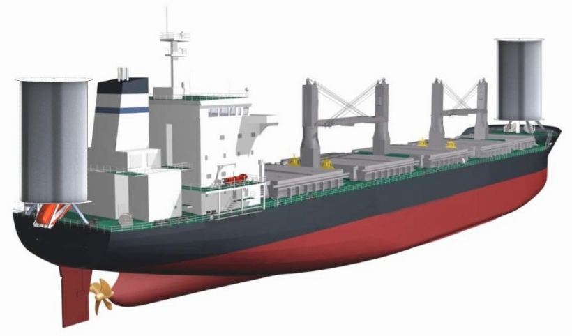
Artists
impression of a cargo ship fitted with the patent applied for Monorotor
system
CONTACTS
Email:
ulrik@bridgeportmagnetics.com
Telephone: +1 203-954-0050
Fax: +1 203-954-0051
A
- Z SAIL AND SOLAR ASSISTED BOATS & SHIPS
ASHINGTON
AQUARIUS
BLACK
MAGIC
ENERGY
OBSERVER
IWSA
- WINDSHIP ASSOCIATION
JAMDA
SOLAR
SAILOR
VINDSKIP
VPLP
WALKER
WINGSAILS
WIND
CHALLENGER
LINKS
& REFERENCE
http://en.wikipedia.org/wiki/Magnus_effect
http://en.wikipedia.org/wiki/Anton_Flettner
http://en.wikipedia.org/wiki/Rotor_ship
http://en.wikipedia.org/wiki/Turbosail
Espacenet.com/Jaques_Cousteau_Turbosail_Patent
US 4630997
http://www.monorotor.com/fuel-savings-with-wind/
http://www.rolls-royce.com/marine/about/environmental_solutions/
http://en.wikipedia.org/wiki/Rolls-Royce_Marine_Power_Operations
|