|
GIANT ROBOT ANT - FRAME or CHASSIS DESIGN
ANTICS - ARDUINO - ARMOUR - ARTWORK - BIOLOGY - BLACK BOX - COMPUTERS - ELECTRONICS - ENERGY - FRAME FORMICARIUM - HEAD - JAWS - JIMMY WATSON - KITS - LEGS - MECHANICS - MOTORS - MOVIE - PHOTOGRAPHY - RASPBERRY Pi R/C DRONE - SENTRY SOFTWARE - SOUND PROOFING - SPACE ROVERS - SPEED - SUSPENSION - TAIL - UKRAINE DRONES - WEAPONS - WARGAMING
|
|
|
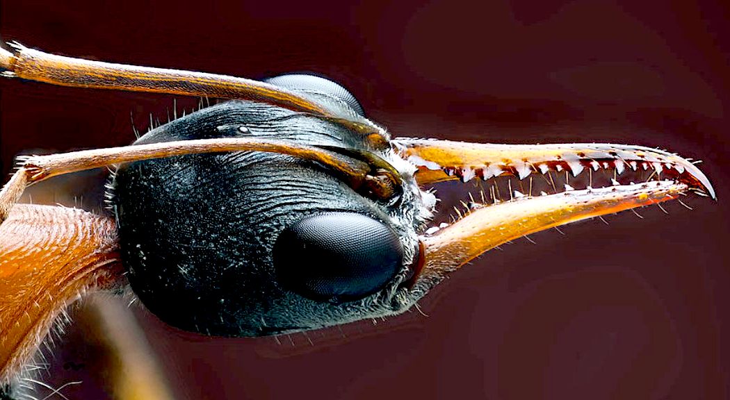
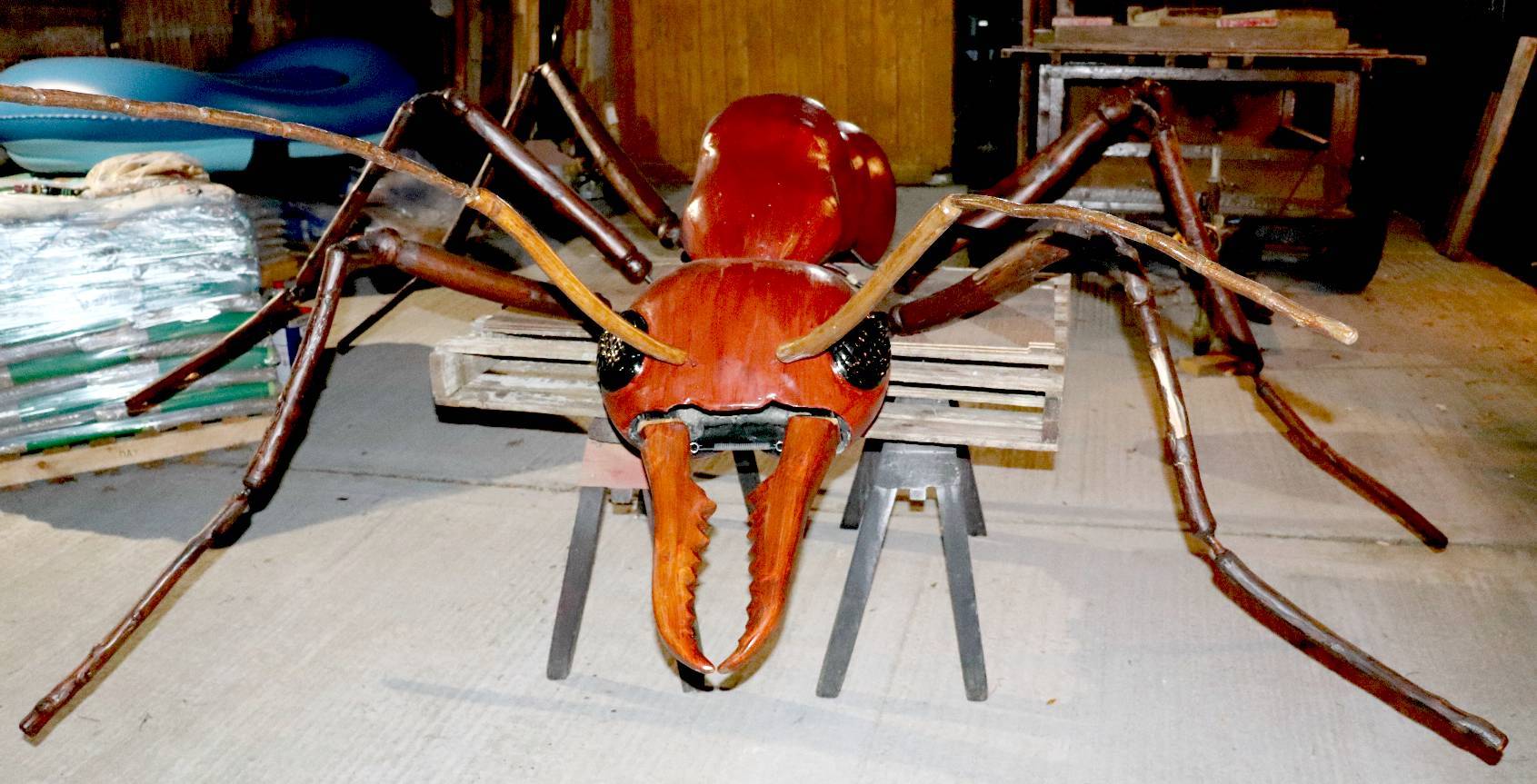
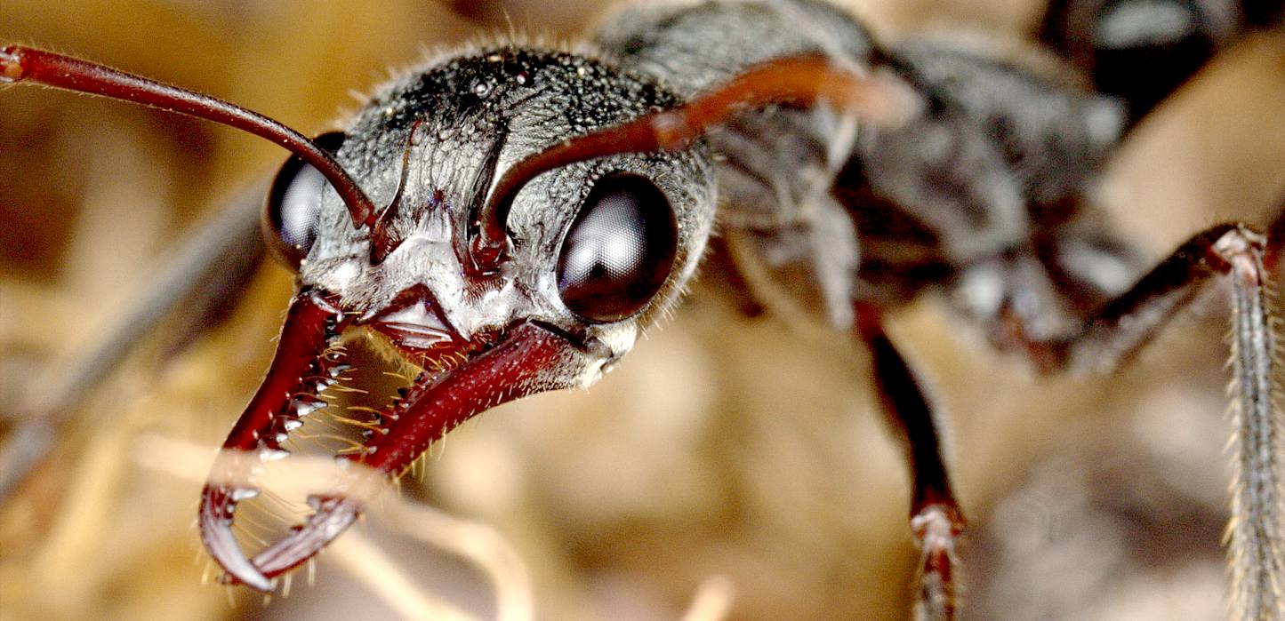
FABULOUS - You can't beat nature. We'll not be aiming to replicate this 100%, but doing an interpretation based on likely evolution with a lot of artistic licence thrown in. As you will see from the sequence below, there is quite a lot of engineering to make a decent frame to work from. We do encourage robot enthusiasts to build their own robot (DIY) and for that reason we explain how it is done. You should though be aware that you will need a workbench, vice, pillar drill, welding equipment, grinders, files and more. If you cannot weld, that is the first hurdle - or ask us to make one for you. It may work out a lot cheaper than equipping a workshop - it is though a lot of fun making a robot yourself - and you will need some handyman skills, even if we make the big steel parts for you.
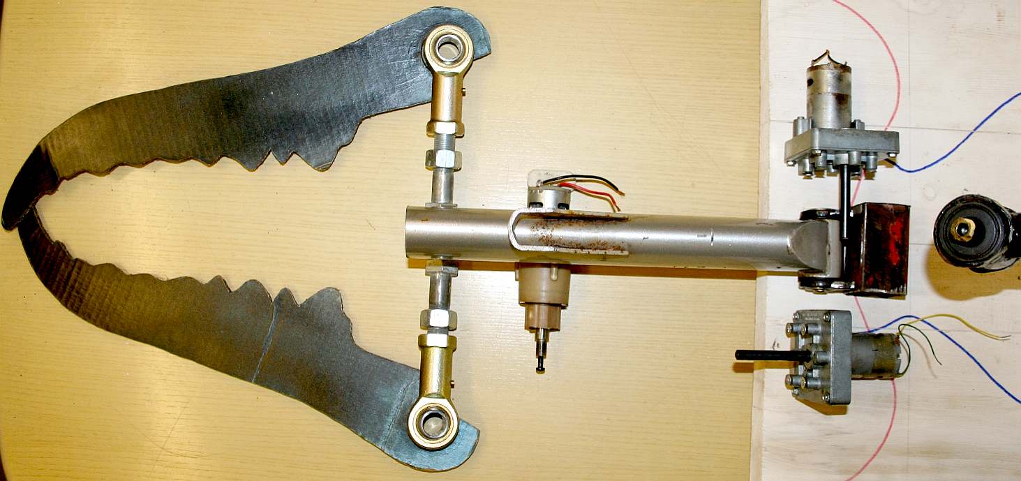
As of 2018, we have revised the chassis design. We are presently conducting a series of experiments using a wooden frame to replace the (rose) hip joints with one of our own design, intended to make the transfer from a rotational drive to a reciprocating stroke more effective.
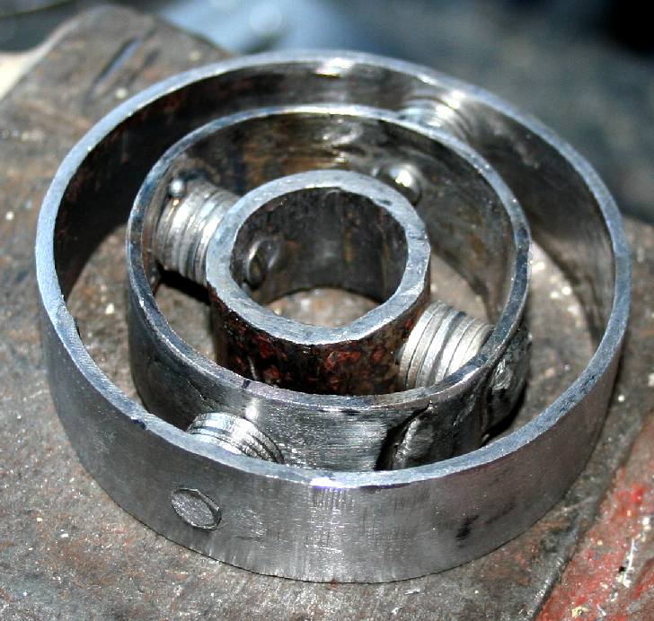
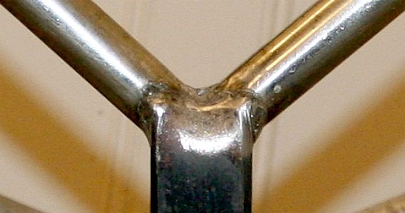
GIMBAL HIP - This is our first experimental inline gimbal joint. Please note that this photograph is copyright © Jameson Hunter Ltd August 31 2018. You will need permission from Jameson Hunter to be able to reproduce it.
CHRISTMAS GIANT ROBOT ANT PROJECT - BUILDING A BRIDGE
The basis of all engineering frame design is a beam or a triangle. A triangle is the simplest structure that cannot change dimensions without the material deforming or failing - giving rise to the space frame, as a light engineering structure. A beam can be solid or hollow, but is straight. Beams are not as light as space-frames, unless the beam is a space-frame. Beams are much cheaper to make when weight is not so important, such as when building houses, skyscrapers or bridges - though in bridge building, cables are used to reinforce the beam roadways - as in suspension bridges.
Sometimes a chassis incorporates a pressure vessel, in which case spheres or tubes are used with spherical ends - to be able to either contain, or withstand pressure, such as in a submarine. This is really all one needs to know to get started, apart from the relative strengths and weaknesses of the materials commercially available. And don't forget the price. Price is really important as the structure gets bigger - and good design can save material.
CHOOSING MATERIALS
For most engineering projects mild steel is the material of choice. It is a superb general purpose material that is easy to drill, machine and weld. It is also economical. But, it corrodes badly; called rusting. Rusting is where the metal combines with oxygen, accelerated by water. So, water is the enemy of steel and most structural engineers.
We are using steel to make the prototype frame. If the design proves to be too heavy, we then have bags of leeway to improve strength and reduce weight. Obviously, a frame made of aluminium or titanium will be lighter and more corrosion resistant. A good selling point if a robot has to withstand all weathers.
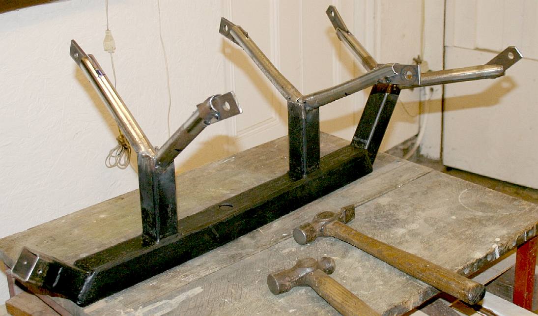
STEEL FRAME - From the base board we can build up a central block to support the steel backbone at the correct height. From here we can insert the subframes for each of the six hip joints. The movement (bearings, spindles and gears) will be mostly coming from underneath this solid section. We are using steel that is thicker than needed for the prototype - just in case adjustments are necessary. Unlike wood, if you get something wrong in steel, it is no big deal to grind out the mistake and weld in another section.
In the case of a robot with a hydraulic movement, the square section (RHS = Rolled Hollow Section) tube will be replaced by a circular section tube, to be able to act as a pressurized fluid reservoir. This little beauty is going to be one tough mother. Compare this frame with the frame of Stompy below; a 6 ton hexapod being built in the USA. Please note that this photograph is copyright © Jameson Hunter Ltd 2015. You will need permission from Jameson Hunter to be able to reproduce it.
TITANIUM
Due to their high tensile strength to density ratio, high corrosion resistance, fatigue resistance, high crack resistance, and ability to withstand moderately high temperatures without creeping, titanium alloys are used in aircraft, armor plating,
naval
ships, spacecraft, and missiles. For these applications titanium alloyed with
aluminium, zirconium, nickel, vanadium, and other elements is used for a variety of components including critical structural parts, fire walls, landing gear, exhaust ducts (helicopters), and hydraulic systems. In fact, about two thirds of all titanium metal produced is used in aircraft engines and frames. The SR-71 "Blackbird" was one of the first aircraft to make extensive use of titanium within its structure, paving the way for its use in modern military and commercial aircraft. An estimated 59 metric tons (130,000 pounds) are used in the Boeing 777, 45 in the
Boeing
747, 18 in the Boeing 737, 32 in the Airbus A340, 18 in the Airbus A330, and 12 in the Airbus A320. The Airbus A380 may use 77 metric tons, including about 11 tons in the engines. In engine applications, titanium is used for rotors, compressor blades, hydraulic system components, and nacelles. The titanium 6AL-4V alloy accounts for almost 50% of all alloys used in aircraft applications.
RECYCLING - As we are having (attempting) a cleanup for the New Year (2016), we are using as much old steel as possible - before our next trip to our local metal dealer. There is a lot of pleasure making something from metal that would otherwise be thrown away. It also lowers our carbon footprint. Those are mountain bike forks and ordinary angle iron, actually steel, but the industry refers to it as angle iron. The bicycle forks are high tensile steel that will work well for the axles. These sections have to be precision marked and drilled. The angle steel will hold the pillow bearings and bolt to the main frame or backbone. The reason for bolting and not welding is to allow us to upgrade or adjust any component - until the prototype is working well. We may want to make a more advanced frame in aluminium or titanium. Or, we may want to beef up the bearings, sprockets and drive chain. The steel bar shown marked into six sections will be made into axle ends.
We have a good track record for recycling materials, click on the picture above to see a show stand we made from redundant materials.
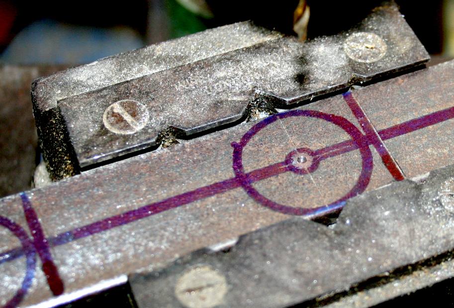
AXLE ENDS - First of all we need to mark out the steel bar accurately to make six axle ends, onto which the spherical leg joints will bolt. We are calling each pair of legs (front pair, middle pair and rear pair) an axle. Hence, front, middle and rear axles. The axle ends will be fitted with 12mm spherical rod ends (rose joints) to begin with but must be capable of taking 14, 16 and 18mm leg joints - depending on the end use of the robot. Always drill a small pilot hole first.
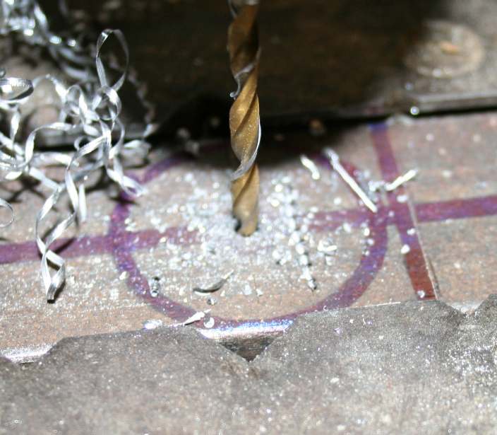
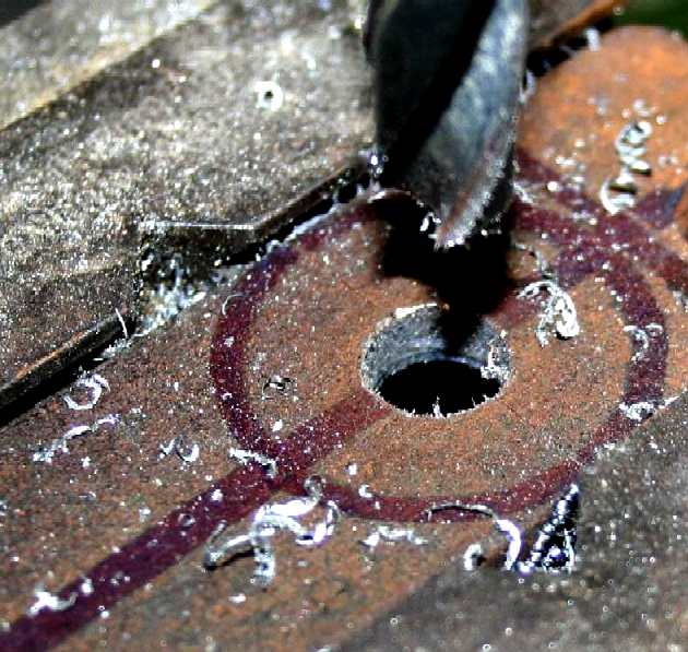
MACHINING - Work your way up through drill sizes in regular stages, 3mm, 5mm, 7.5mm, 10mm, 11mm and 12mm. There is no need to ream the holes because the rose joints will be bolted through and tight, this is not a bearing surface. The fit just needs to be tight. Use cutting fluid to get a clean hole and help keep your drills working well for longer.
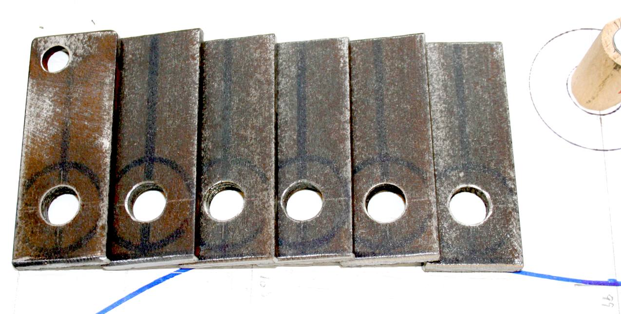
PRODUCTION RUN - You can see how we saved workshop time by marking out and drilling all six axle ends before we cut the steel bar into individual parts.
HSS HACKSAW - Sometimes things have to be done by hand. Recycling material sometimes means that the thinnest cut is needed. If this bar had been cut into individual mounting plates with a carborundum bladed chop saw, we'd have lost about an inch (25mm) of steel. By using a hacksaw we only lost 5/16" (8mm).
HIP JOINTS - MOUNTING PLATES - Here are the six ball joint mounting plates all ready to be welded to the axles. They will need to be ground a little before joining, because even a little surface rust can affect the quality of a weld.
ROSE JOINTS - We are modifying the standard rose joint so that the forces pass through the ball fulcrum acting like a lever in combination with a crank action. As far as we know this has not been done before. As nothing like the mechanism we need exists, it means that we have to re-manufacture the item to suit. Rose joints are capable of handling very heavy loadings.
HISTORY - The spherical rod end bearing was developed by the Germans in World War II. A German plane was shot down by the British in early 1940 and when it was examined they found this kind of joint in use in the aircraft's control systems. In the USA, the H.G. Heim Company was given an exclusive patent to manufacture these joints, while in the UK the patent passed to Rose Bearings Ltd. From this rather odd monopoly situation of the manufacturers in their respective markets, their names were used to describe the product. Hence, the terms "heim joint" (USA) and "rose joint" (UK) became synonymous with their product. Even after the patents ran out, the common names stuck. Though, "rose joint" is a registered trademark of Rose Bearings Ltd. Normally patents could not be granted for a product that somebody else had not only invented, but used in public in an airplane.
Originally used in aircraft, the rod end bearing may be found in cars, trucks, race cars, motorcycles, lawn tractors, boats, industrial machines, go-karts, radio-control helicopters, and many more applications. A rose joint is a mechanical articulating joint. Such joints are used on the ends of control rods, steering links, tie rods, or anywhere a precision articulating joint is required. A ball swivel with an opening through which a bolt or other attaching hardware may pass is pressed into a circular casing with a threaded shaft attached. The threaded portion may be either male or female. A female thread is shown above.
CHEMISTRY
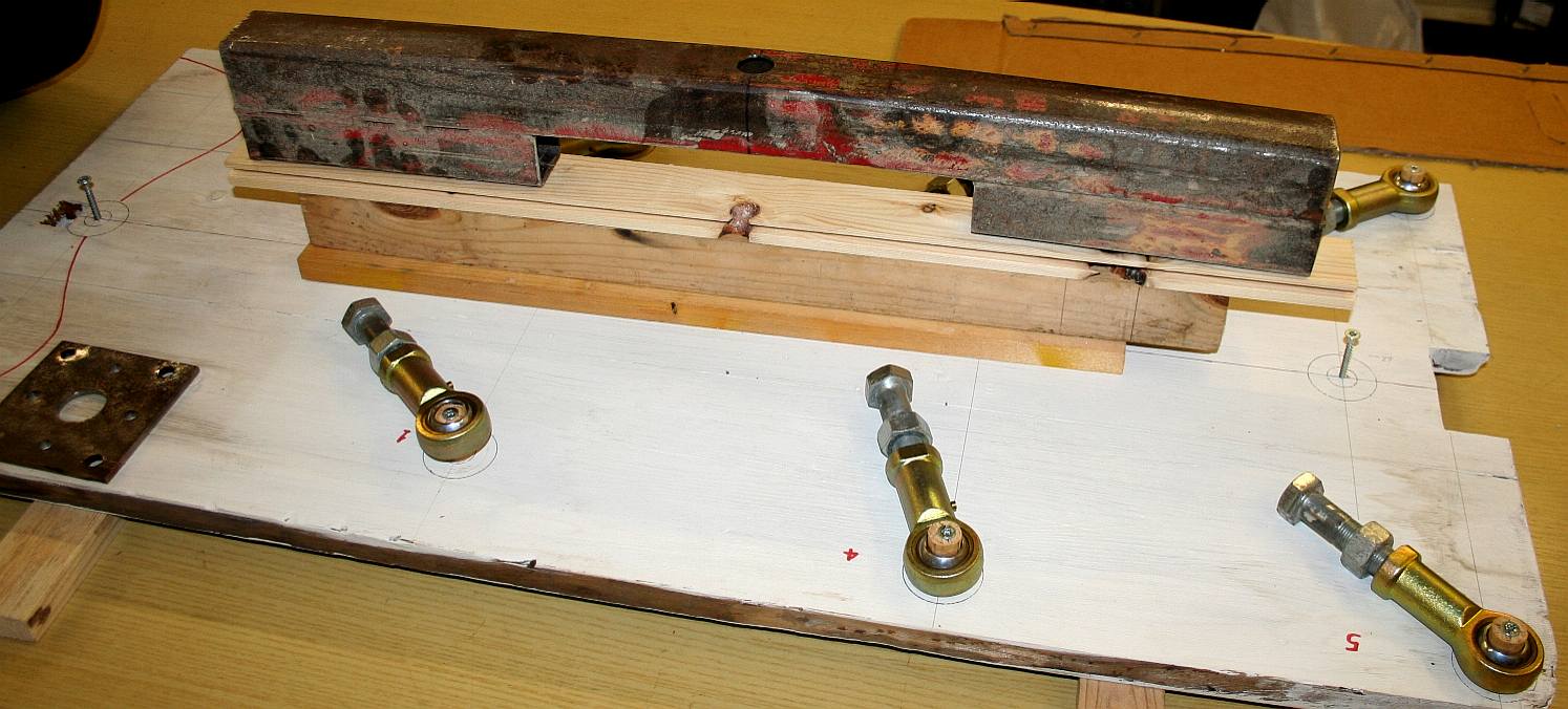
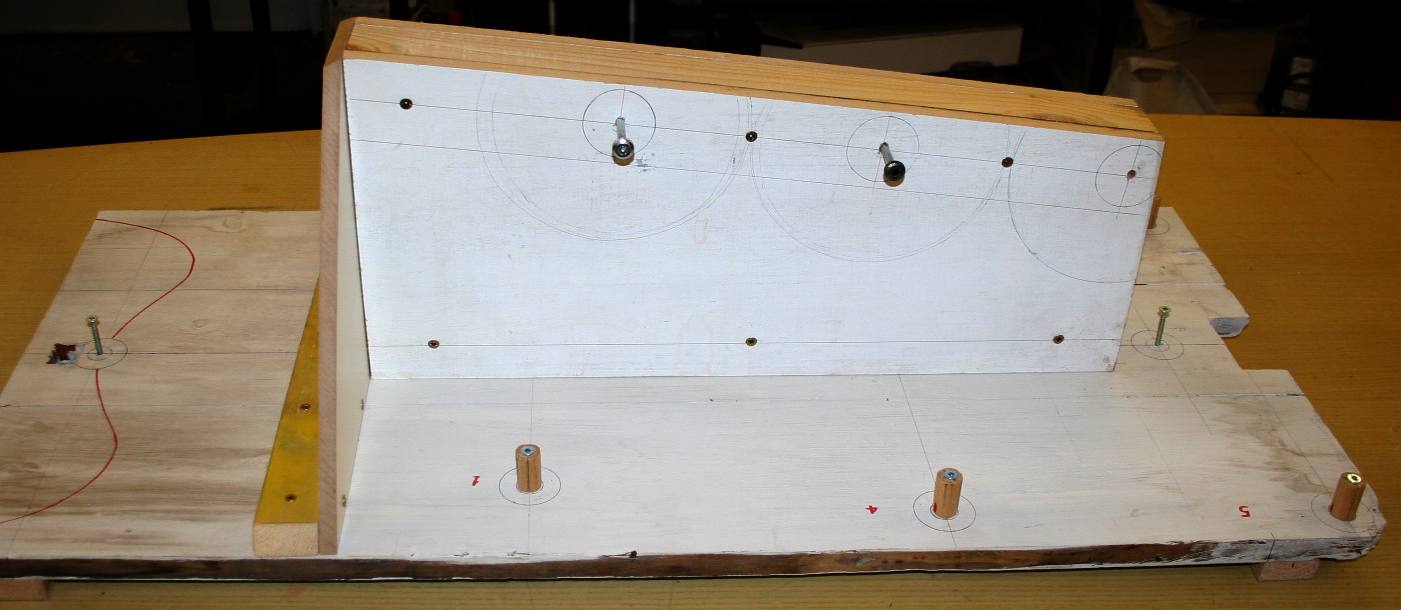
JIG DEVELOPMENT - Alignment of the leg bearings to the driving cranks is essential. The only way to achieve this time and time again is to make sure that your jig is accurate - to cabinet making standards. You can see above that the pine planking has been reinforced underneath and braced on top. The angle of the flat timber top is that of the backbone of the chassis/frame. This robot is a vehicle of course, so 'chassis' may be more correct than 'frame.' Please note that this photograph is copyright © Jameson Hunter Ltd 2015. You will need permission from Jameson Hunter to be able to reproduce it.
JIG/BUCK DEVELOPMENT - An engineering jig is sometimes called a buck, after the wooden horses in gymnasiums. Usually the term: "buck" refers to a wooden frame to make car panels from. You can see why from this photograph. Please note that this photograph is copyright © Jameson Hunter Ltd 2015. You will need permission from Jameson Hunter to be able to reproduce it.
ROUGH LAYOUT - The jig allows us to visualize how the mechanical parts will work together. As such it is a major design tool and a time saver. Please note that this photograph is copyright © Jameson Hunter Ltd 2015. You will need permission from Jameson Hunter to be able to reproduce it.
MECHANICAL CLEARANCE - When designing a frame it is important to leave plenty of room for rotating parts that may expand somewhat at high revolution speeds or temperatures. It may work on paper, but we like to check in real time. Please note that this photograph is copyright © Jameson Hunter Ltd 2015. You will need permission from Jameson Hunter to be able to reproduce it.
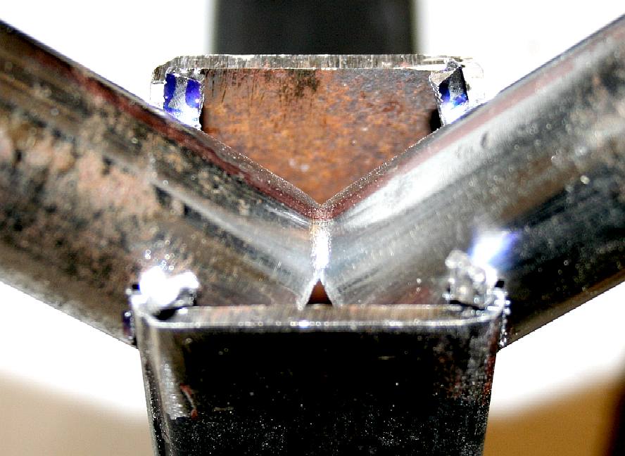
STEEL BACKBONE - The parts of the robot frame are seen here rough cut in 40 and 50mm box section steel, placed onto a working drawing. On production models the steel will be much thinner section and may be replaced by aluminium or titanium. A backbone design which is easier to work with during development, may give way to a monocoque type chassis - one step closer to the exoskeleton design of the live insect. Engineering is down to cost. The more exotic you go, the more expensive - until you reach Formula 1 racing and then NASA spacecraft prices. We are looking for a happy medium to make these machines affordable for robot enthusiasts and students on a budget. Please note that this frame is Design Copyright and that this photograph is Copyright © Jameson Hunter Ltd 18 December 2015. All rights reserved. You will need permission from Jameson Hunter to be able to reproduce it.
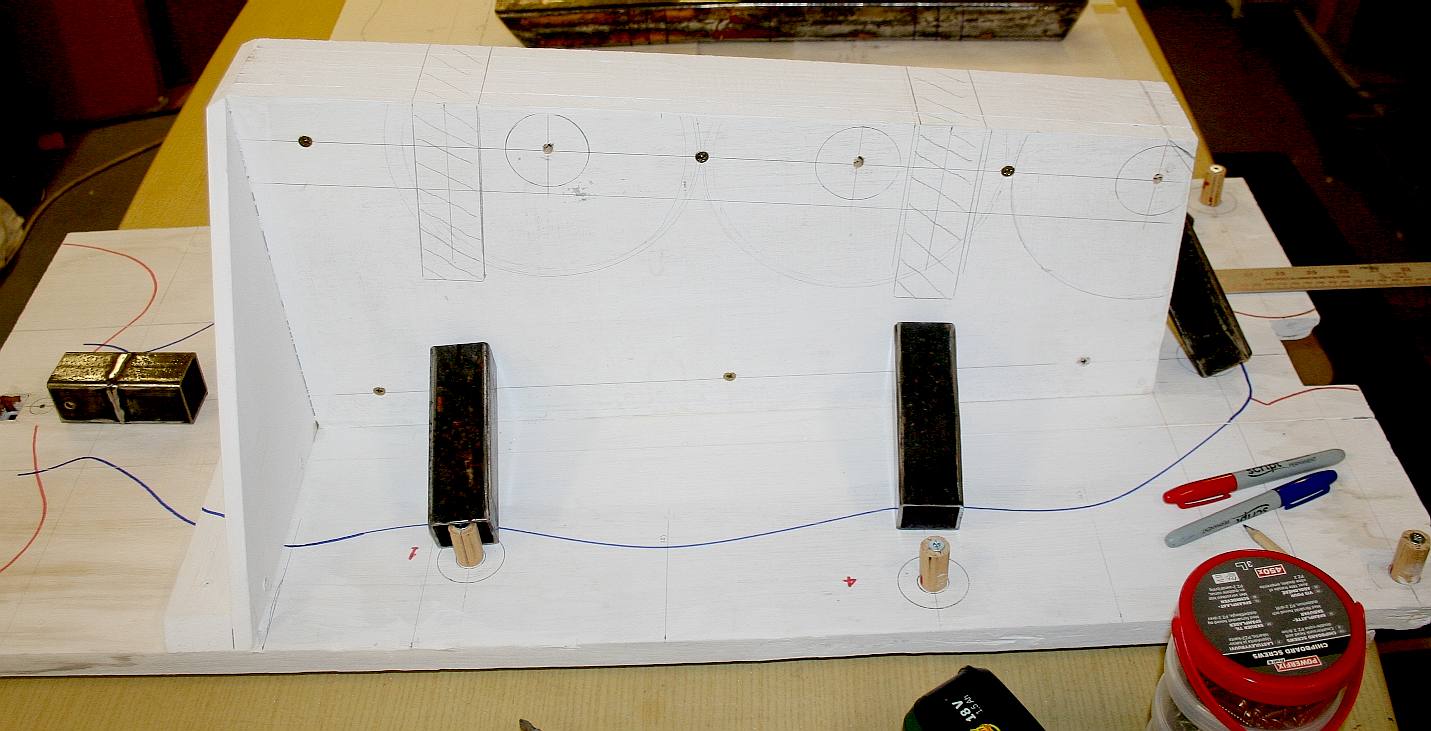
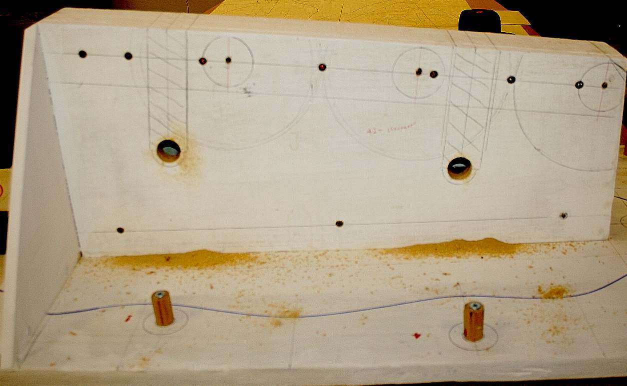
JIG DETAILS - The buck is further refined. Slots are marked to accept the down-tubes from where the axle tubes may be fitted. You can see the sections marked with cross hatching that are to be cut out next. Please note that this frame is Design Copyright and that this photograph is Copyright © Jameson Hunter Ltd 18 December 2015. All rights reserved. You will need permission from Jameson Hunter to be able to reproduce it.
JIG DETAILS - The axle locations have been machined out using a circular cutter on a power drill. Next comes the sawing of the cross-hatched slots. Please note that this frame is Design Copyright and that this photograph is Copyright © Jameson Hunter Ltd 18 December 2015. All rights reserved. You will need permission from Jameson Hunter to be able to reproduce it.
WOODWORK - When working in wood with many operations, it is essential to take precautions to get your cuts perfect first time. Use a sharp pencil and saw - and concentrate on each cut. Check on both sides of the work piece frequently, in case adjustment needs to be made. Better to catch it before a cut is complete, than find the cut is wonky. Please note that this frame is Design Copyright and that this photograph is Copyright © Jameson Hunter Ltd 18 December 2015. All rights reserved. You will need permission from Jameson Hunter to be able to reproduce it.
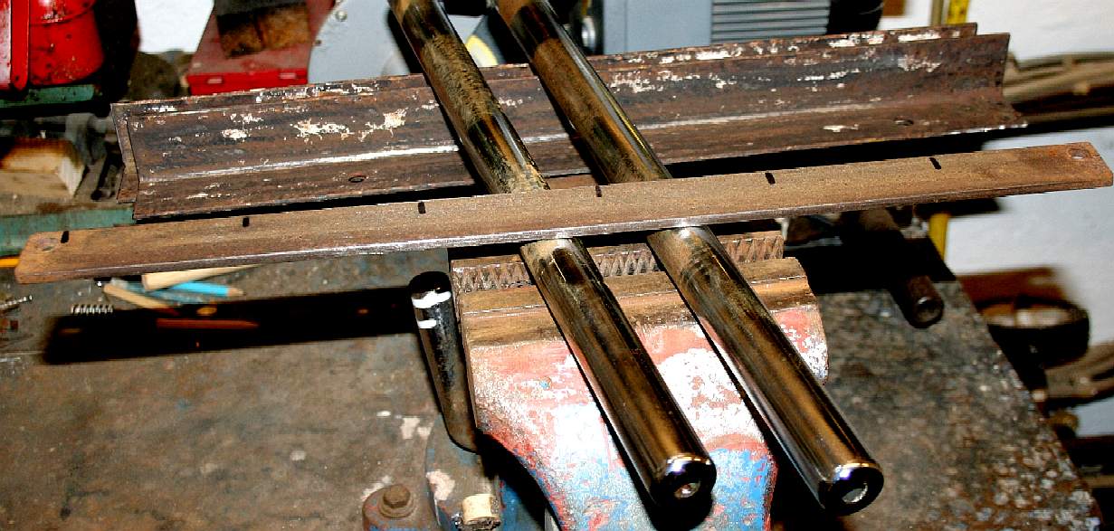
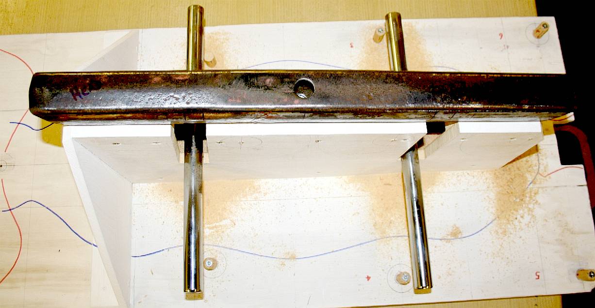
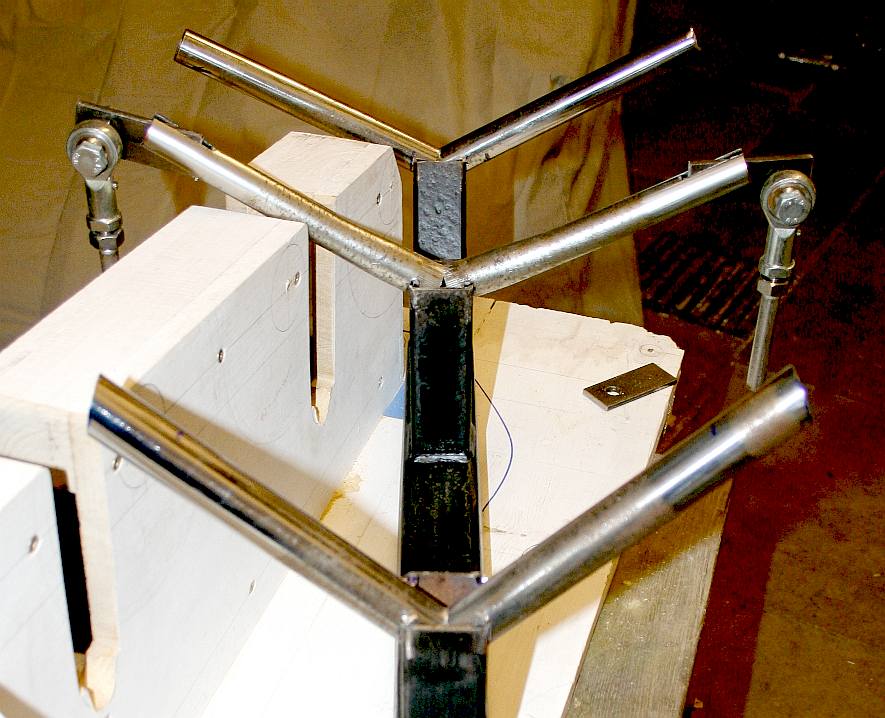
JIG DETAILS - With the slots cut we placed the high tensile steel tubes in place to make sure they are parallel - they are. These tubes need to be cut and formed to angle down to the ball joint locations. Steel ends will need to be prepared (drilled) and welded in place, and the axles welded to the down tubes. That is why a jig is so important. All the component parts are held in the right place for welding. Please note that this frame is Design Copyright and that this photograph is Copyright © Jameson Hunter Ltd 18 December 2015. All rights reserved. You will need permission from Jameson Hunter to be able to reproduce it.
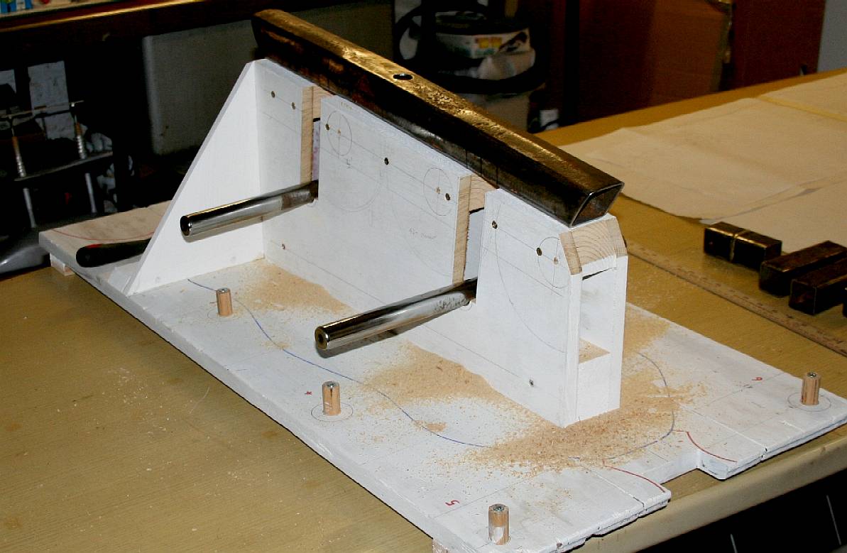
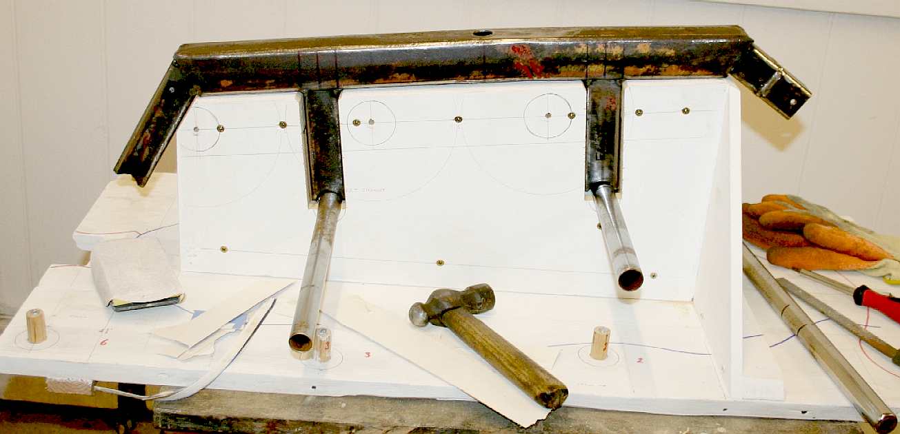
JIG DETAILS - December 21 2015 - In this picture you can see how much the axles need to be turned down to be at the correct height for the leg joints. Please note that this frame is Design Copyright and that this photograph is Copyright © Jameson Hunter Ltd 18 December 2015. All rights reserved. You will need permission from Jameson Hunter to be able to reproduce it.
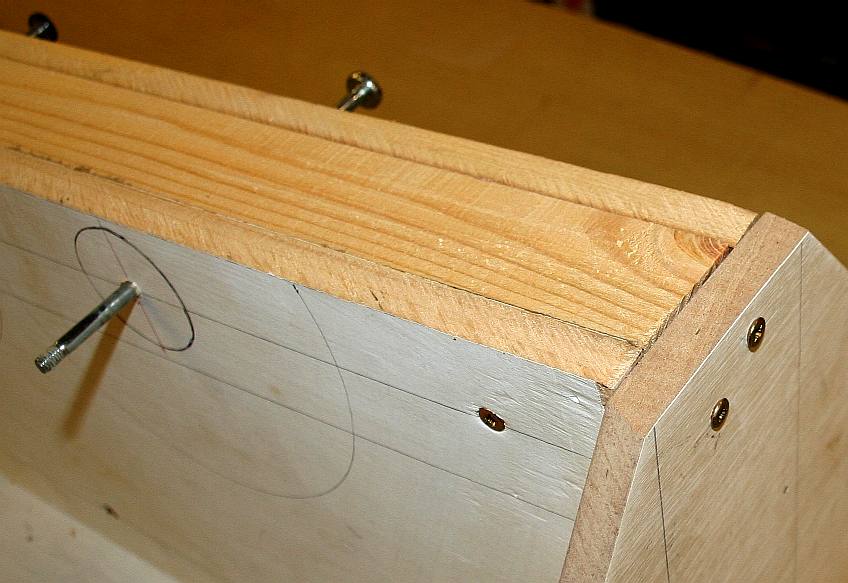
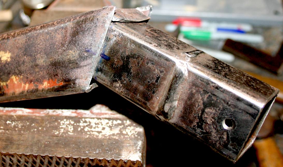
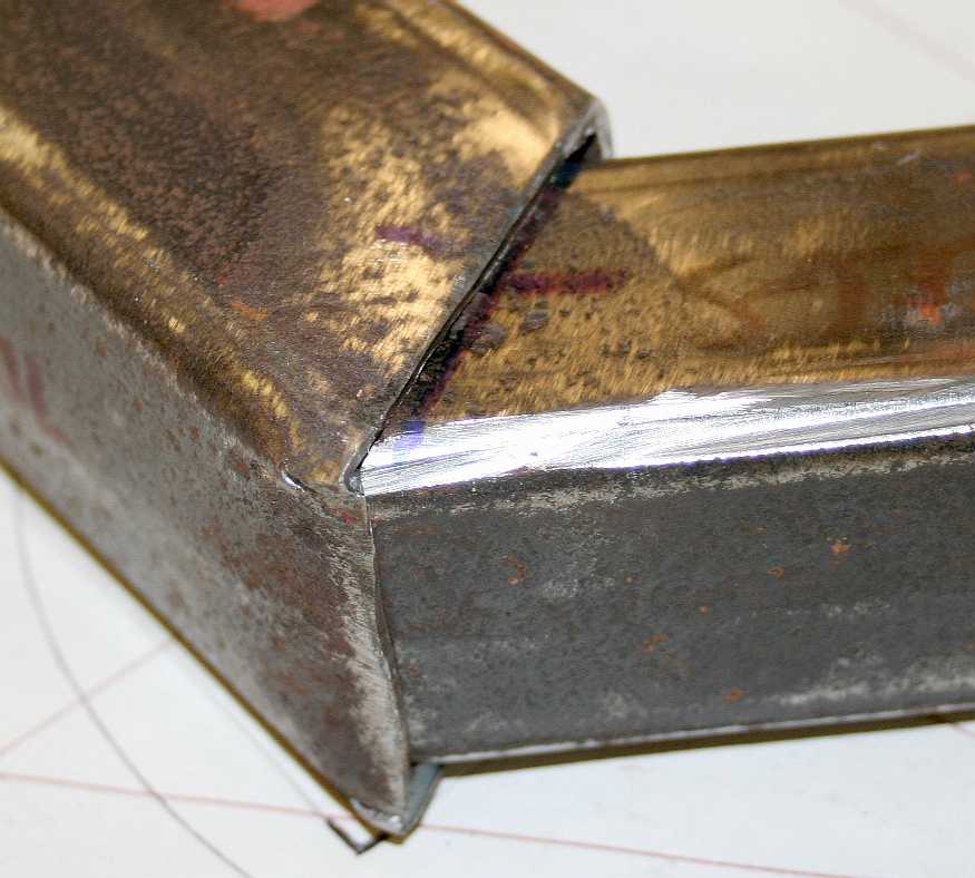
NECK JOINT - This is the head end of the backbone tube. We need to go from a 50mm section to an interference fit on a 40mm tube, before welding. One way to do this is using a blacksmiths hammer to close the 50mm tube down on to the 40mm tube. We had to use a hacksaw to cut a flap that we could fold down to meet the smaller section tube.
NECK JOINT - As you can see from the picture above, the backbone has been closed tightly onto the steel neck tube. This will make welding easy and ensure a strong join using as little filler wire as possible. A further reduction will be needed as the neck proceeds from the 40mm tube to the head hinges and/or swivel. We will not be using a spherical joint here. This joint will be capable of lifting 180 kg (400lbs) or two 14 stone people. It is down to the designer what safety factor he or she builds into a design. Formula 1 cars sometimes have a safety factor of just 1, where family cars might have a safety factor of 4. That of course means that the family car will weigh more, but also that a formula one car is unlikely to withstand constant use without failing. We are taking the middle ground with this design.
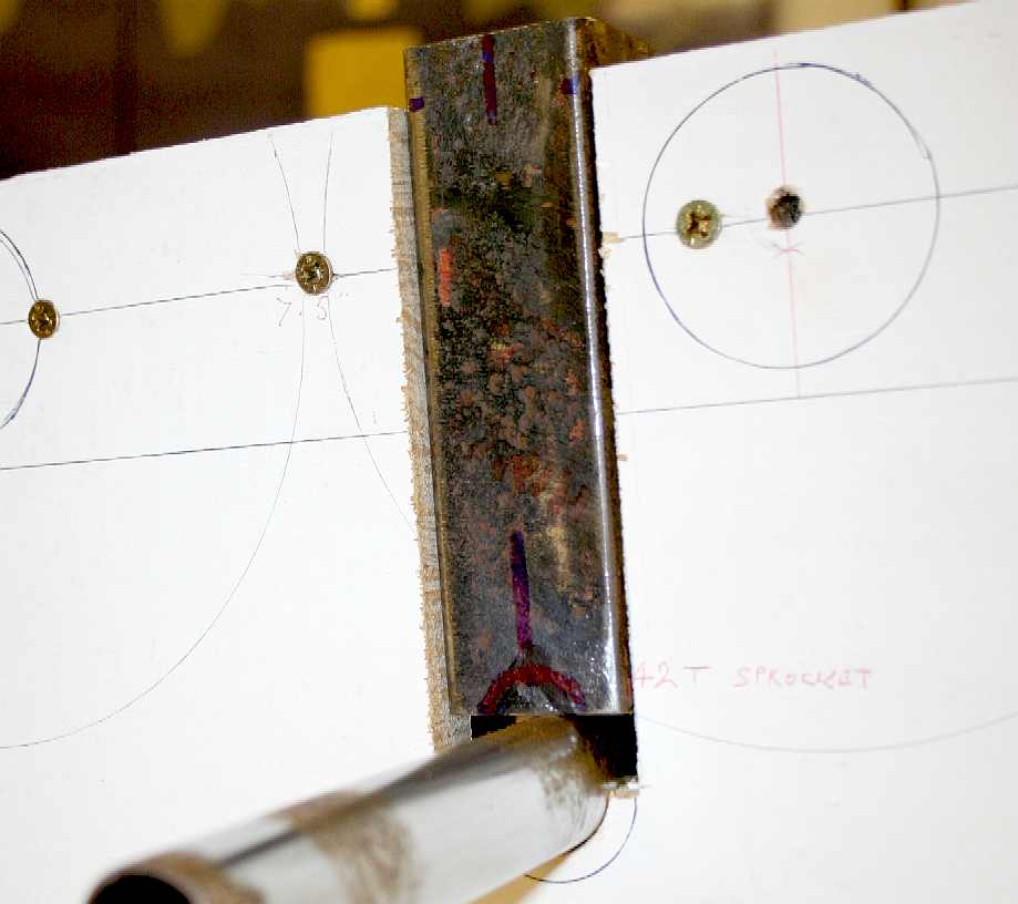
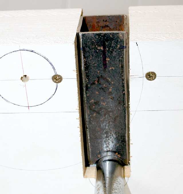
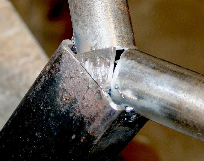
AXLE DOWN TUBES - [LEFT] Steel box section is placed on top of ax axle tube and marked. [RIGHT] The same steel tube now fits perfectly flush with the bed for the main frame tube, and also fits snugly around the axle tube for welding. This is the value of a jig. You can make pieces and test them for size - see how the radius was cut below. Please note that this frame is Design Copyright and that this photograph is Copyright © Jameson Hunter Ltd 18 December 2015. All rights reserved. You will need permission from Jameson Hunter to be able to reproduce it.
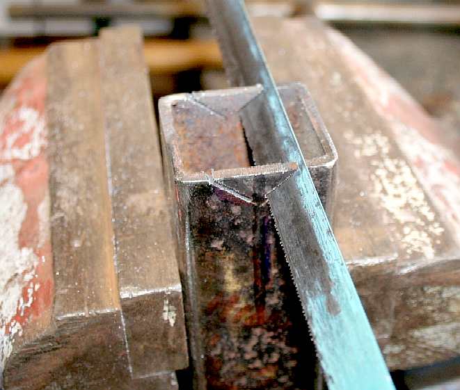
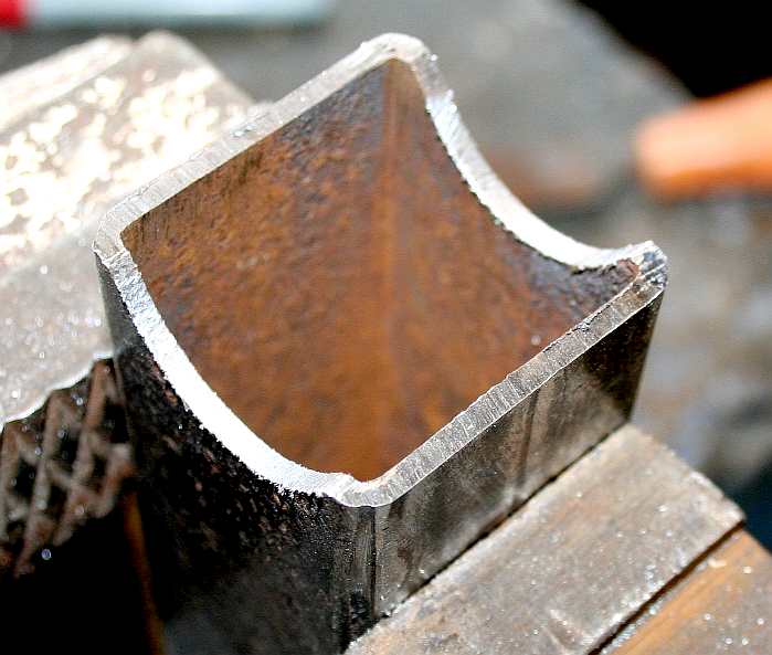
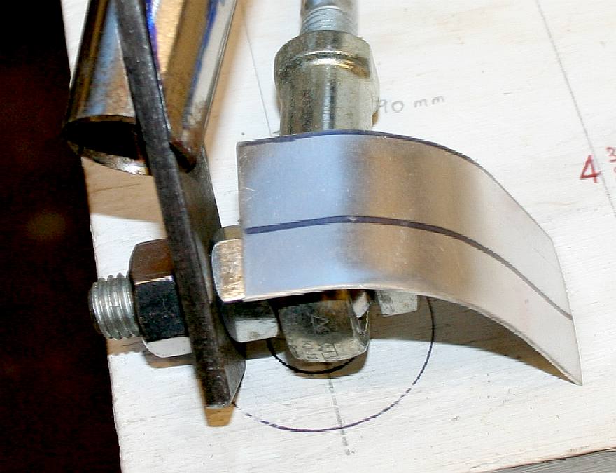
AXLE DOWN TUBES - [LEFT] In order to get a radius to fit around the axles, a 'V' is cut in the lower end of the steel tube using an ordinary HSS hacksaw blade. [RIGHT] the 'V' is then filed to shape with a half-round file, until the felt marker looks right, and then it is offered up for size. This Please note that this frame is Design Copyright and that this photograph is Copyright © Jameson Hunter Ltd 18 December 2015. All rights reserved. You will need permission from Jameson Hunter to be able to reproduce it.
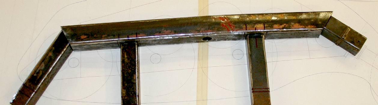
TAIL JOINT - We are getting ready to weld the axle down tubes, neck and tail tubes to the main frame. You can see in the picture above that the tail end on the 50mm backbone has now been shaped around the 40mm tail tube. Please note that this frame is Design Copyright and that this photograph is Copyright © Jameson Hunter Ltd 18 December 2015. All rights reserved. You will need permission from Jameson Hunter to be able to reproduce it.
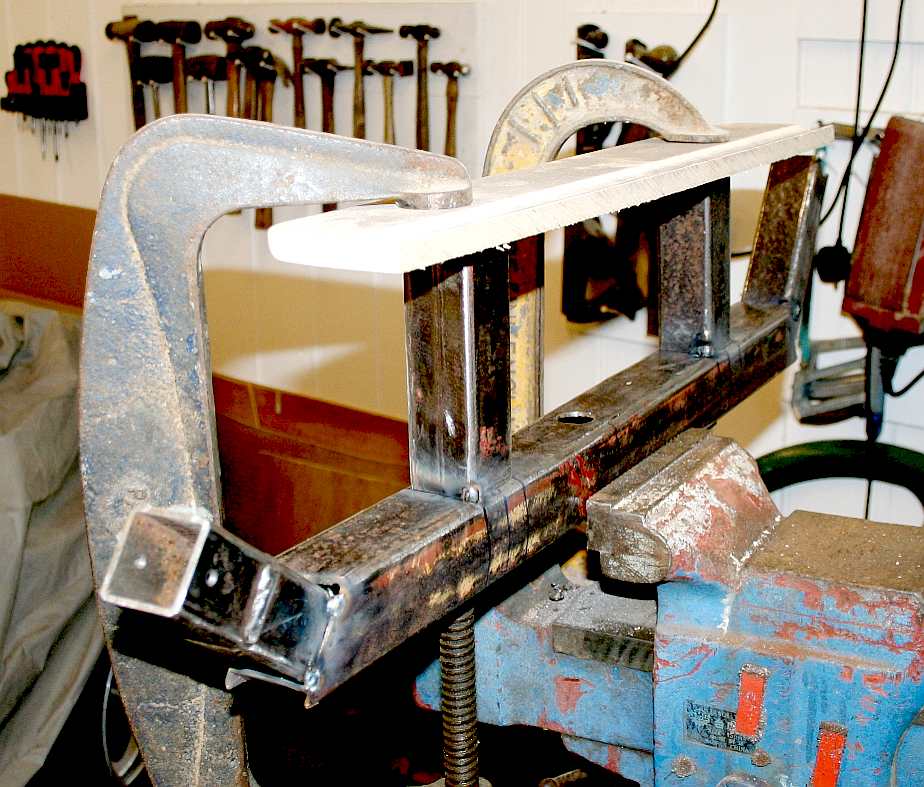
TACK WELDS - The tubes are clamped into position and tack welded. Never weld up a frame without checking the angles and alignment. Once tacked, we can offer the assembly up to the jig and make sure it fits. Please note that this frame is Design Copyright and that this photograph is Copyright © Jameson Hunter Ltd 18 December 2015. All rights reserved. You will need permission from Jameson Hunter to be able to reproduce it.
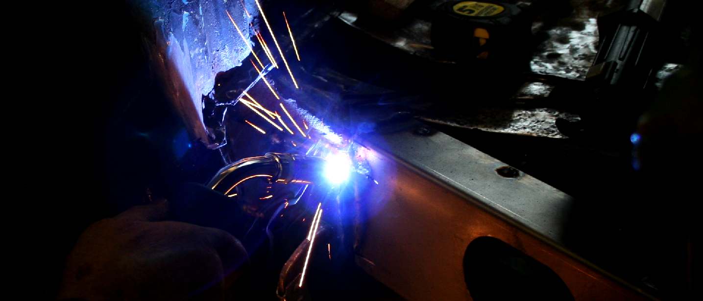
WELDING - One of the essential skills that every large scale robot builder must master is the art of welding. our advice is to get your hands on the best equipment you can afford. It may hurt when you purchase it, but quality welds are the backbone of any engineering project involving metal frame fabrication. Copyright © photograph Bluebird Marine Systems Ltd. All rights reserved.
JIG & FRAME - It fits - not 100%, but within reasonable limits, such that clearances will be taken up by weld, when the axles are joined to the down tubes. Please note that this frame is Design Copyright and that this photograph is Copyright © Jameson Hunter Ltd 18 December 2015. All rights reserved. You will need permission from Jameson Hunter to be able to reproduce it.
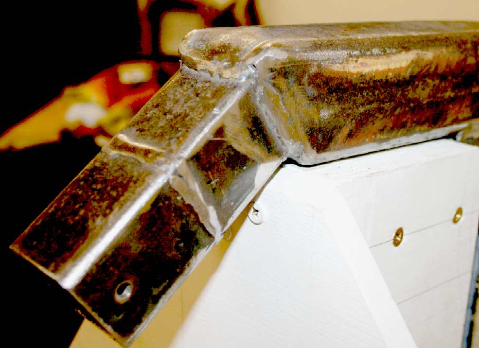
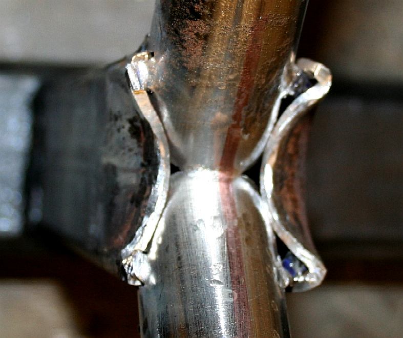
WELDED FRAME ENDS - If we wanted to improve on the weld finish for polishing, we'd need to TIG, instead of MIG weld. Generally grinding a weld weakens the join, but we will be handling this frame a lot when fitting the transmission, so felt it was better to remove any rough edges. The frame is seriously over-strong anyway. Please note that this frame is Design Copyright and that this photograph is Copyright © Jameson Hunter Ltd 18 December 2015. All rights reserved. You will need permission from Jameson Hunter to be able to reproduce it.
ANTI RUST TREATMENT - 23 December 2015 - Before going any further, it's time to treat the rust. Grind and sand the steel frame and then coat liberally with a rust converter. If the steel is fresh from the mill, you may want to remove the scale so that a good quality primer will take to the steel. If we made/make this frame in stainless steel, aluminium or titanium, painting is not necessary. A polished frame would look awesome. Please note that this frame is Design Copyright and that this photograph is Copyright © Jameson Hunter Ltd 18 December 2015. All rights reserved. You will need permission from Jameson Hunter to be able to reproduce it - except where the picture is used for private study or as part of an educational project. JHL would though appreciated a mention and link back to the appropriate page in return for permission to use.
LAYOUT - 24 December 2015 - Putting things into perspective. It helps, that having made a component, such as the main frame, to offer it up to the working drawings to be sure all is good. More welding next. Please note that this frame is Design Copyright and that this photograph is Copyright © Jameson Hunter Ltd 18 December 2015. All rights reserved. You will need permission from Jameson Hunter to be able to reproduce it - except where the picture is used for private study or as part of an educational project. JHL would though appreciated a mention and link back to the appropriate page in return for permission to use.
FETTLING - Having got the angles right, we need to cut a slot in the steel tubing for the chassis down tube to seat into. This will make for a stronger frame. Please note that this frame is Design Copyright and that this photograph is Copyright © Jameson Hunter Ltd 18 December 2015. All rights reserved. You will need permission from Jameson Hunter to be able to reproduce it.
CUTTING - Mark out approximately in felt tip and cut out a section that is too small. Offer the axle up to the chassis in the jig and remark for a second cut. It is better to spend a bit more time doing the seats in stages, than to rush at it and cut out too much metal. We need the geometry to be spot on if this machine is going to run at a good pace.
AXLE MOCK UP - December 27th - More progress. Working in steel is time consuming. Prototyping demands constant fine adjustment. Once the angles are all worked out it is not so bad - working them out means many cups of tea and coffee - to gather ones thoughts and come back refreshed for another shaping session. Imagine trying to measure these angles without a solid wooden platform as a reference point. It is possible, but would take so much longer. That is the whole point of a buck. Please note that this frame is Design Copyright and that this photograph is Copyright © Jameson Hunter Ltd 20 December 2015. All rights reserved. You will need permission from Jameson Hunter to be able to reproduce it.
JOINERY IN STEEL - Here we test the tolerances. Two slots are cut for the down-tube end to sit in - seen here upside down. It's good enough to weld - a nice tight interference fit. The open ends will be beaten down onto the tube during the welding procedure, and if needed, another plate added to cap the join. It will be strong. But then this beam (or axle) has to cope with legs revolving at 15 cycles a second at full sprint speed. That is 900 revolutions a minute for legs that are over a meter in length. The racing legs will have to be super light and super strong. How do insects cope?
BY THREE - Repeat that fit-up for each axle - and put the assembly into the buck to be sure all is square. Slots for the hip plates need to be cut. We can tell you that this was the most tricky part, requiring a whole lot of trial and error. Take your time when fettling. Most people rush and cut out too much, then have to start again. If we go for the robotic world running record, we'll have to make this all over again in titanium - with additional stiffening members. We'll use the same craftsman - as he now knows the procedure. They do this with hand built cars like Aston Martin and Morgan, especially on the bodywork and trims. Please note that this frame is Design Copyright and that this photograph is Copyright © Jameson Hunter Ltd 20 December 2015. All rights reserved. You will need permission from Jameson Hunter to be able to reproduce it.
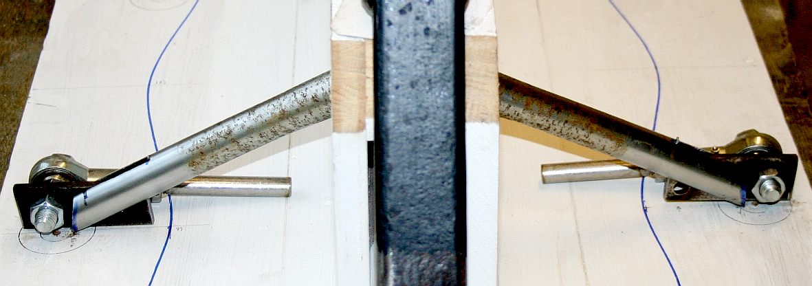
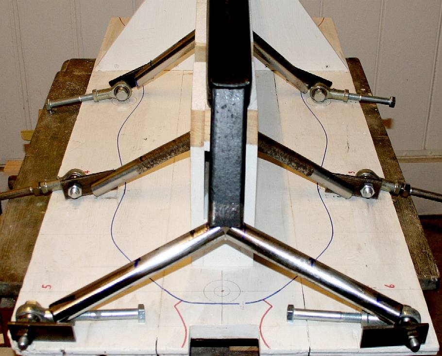
BACK TO THE BUCK - Flip her over and slot back into the jig. A couple more slots have been cut and the test rose joints (spherical rod ends) loosely bolted in place. These are to be replaced with 14mm units. We're just waiting for a 14mm HSS tap to arrive. Would you believe that we had 12, 16 and 18mm taps, and a selection of imperial taps, but could not find the one we needed. Thank heavens for the internet and a good delivery network. We've now decided to make some of the parts in aluminium: Legs and the bearing block sub-frame. Please note that this frame is Design Copyright and that this photograph is Copyright © Jameson Hunter Ltd December 2015. All rights reserved. You will need permission from Jameson Hunter to be able to reproduce it.
SHIELDING - December 31 2015 - When welding near machine parts, either remove them or shield them against spatter - especially precision items like ball joints. Please note that this frame is Design Copyright and that this photograph is Copyright © Jameson Hunter Ltd December 31 2015. All rights reserved. You will need permission from Jameson Hunter to be able to reproduce it.
TACK WELDED - December 31 2015 - The whole frame is tack welded. It is better to rotate the work piece when welding so that the welds are made from above, or up, or downhill if that is not practical. Please note that this frame is Design Copyright and that this photograph is Copyright © Jameson Hunter Ltd 31 December 2015. All rights reserved. You will need permission from Jameson Hunter to be able to reproduce it.
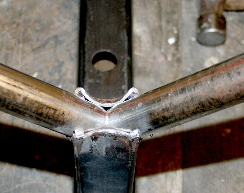
FORGING & FILLING - December 31 2015 - [LEFT] The steel down tubes were shaped around the axle tubes while hot - no extra plate was needed for the two front axles. [RIGHT] Where there was a gap that our welder felt uncomfortable about on the rear axle, a triangle of steel was cut to size and welded in. Our welder is a skilled blacksmith. Before attempting a project like this, practice on some old steel. Better that, than ruining your frame. Please note that this frame is Design Copyright © Jameson Hunter Ltd.
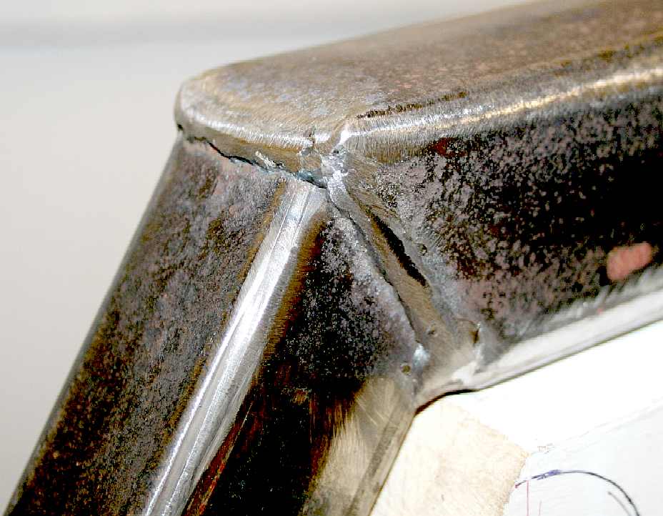
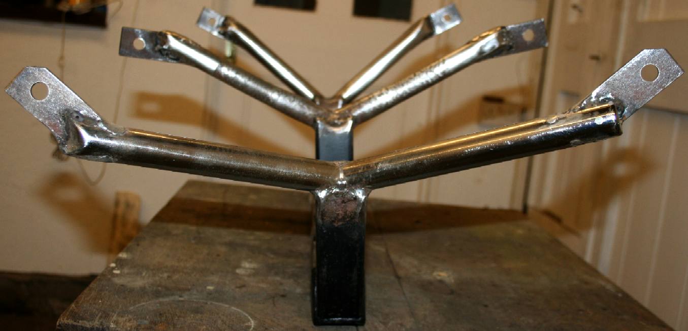
BLACKSMITHING - December 31 2015 - The frame was tack welded, forged hot & cold and finally when all looked right, welded all round and the spatter polished out with a flappy disc. This is advisable where the frame will be handled quite a bit. Remove all sharp edges for safety. Welding like this makes for a very strong frame. The robot will be more than capable of carrying a human on its back or in its jaws for movie stunt work. That gives you some idea of the payload carrying capacity that could make these hexapods extremely versatile.
WELDING COMPLETE - January 1 2016 - The frame was lightly sanded to remove any surface rust and give paint a chance to adhere. Thoroughly wire brush welded joins to remove the corrosive haze. If you leave that grey/white film, it will cause rusting and pickle under any paint. Please note that this frame is Design Copyright and that this photograph is Copyright © Jameson Hunter Ltd January 1 2016. All rights reserved. You will need permission from Jameson Hunter to be able to reproduce it.
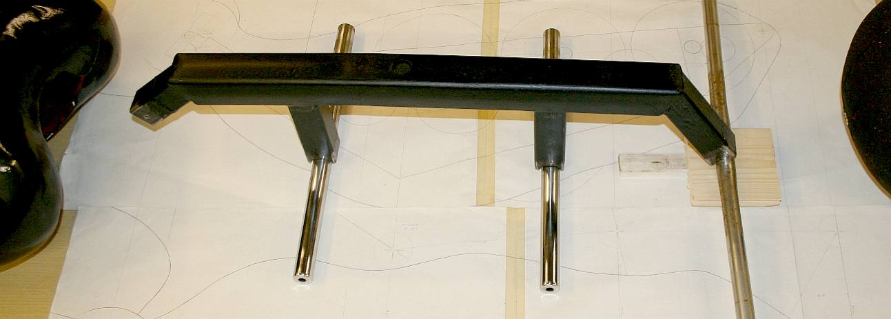
QUALITY CONTROL - January 1 2016 - The frame has been coated with rust converter/primer and compared to the full size paper working drawings. Please note that this frame is Design Copyright and that this photograph is Copyright © Jameson Hunter Ltd January 1st 2016. All rights reserved. You will need permission from Jameson Hunter to be able to reproduce it.
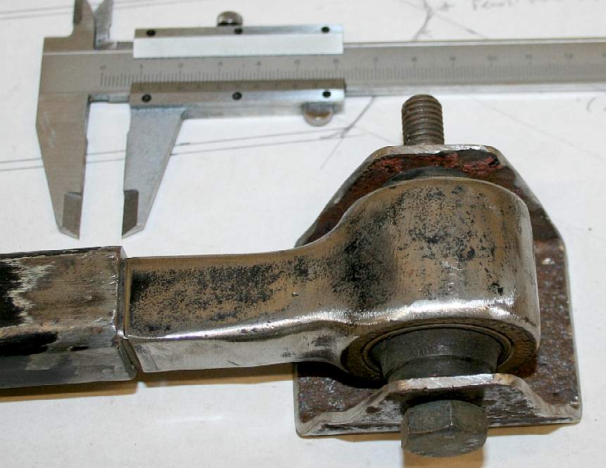
TAIL BRACKET - January 31 2016 - A steel bracket is made to accept an 11mm high tensile steel bolt. The drop forged suspension joint is rubber bushed to insulate the batteries from jarring as the robot operates at high speed.
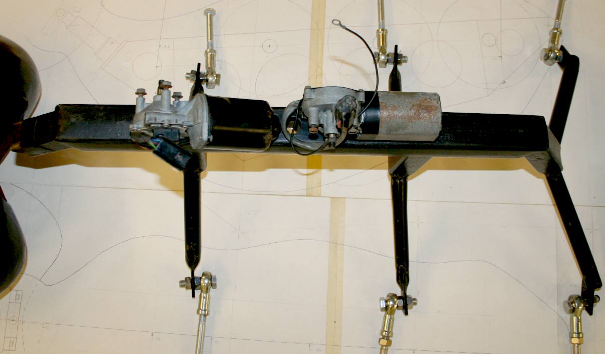
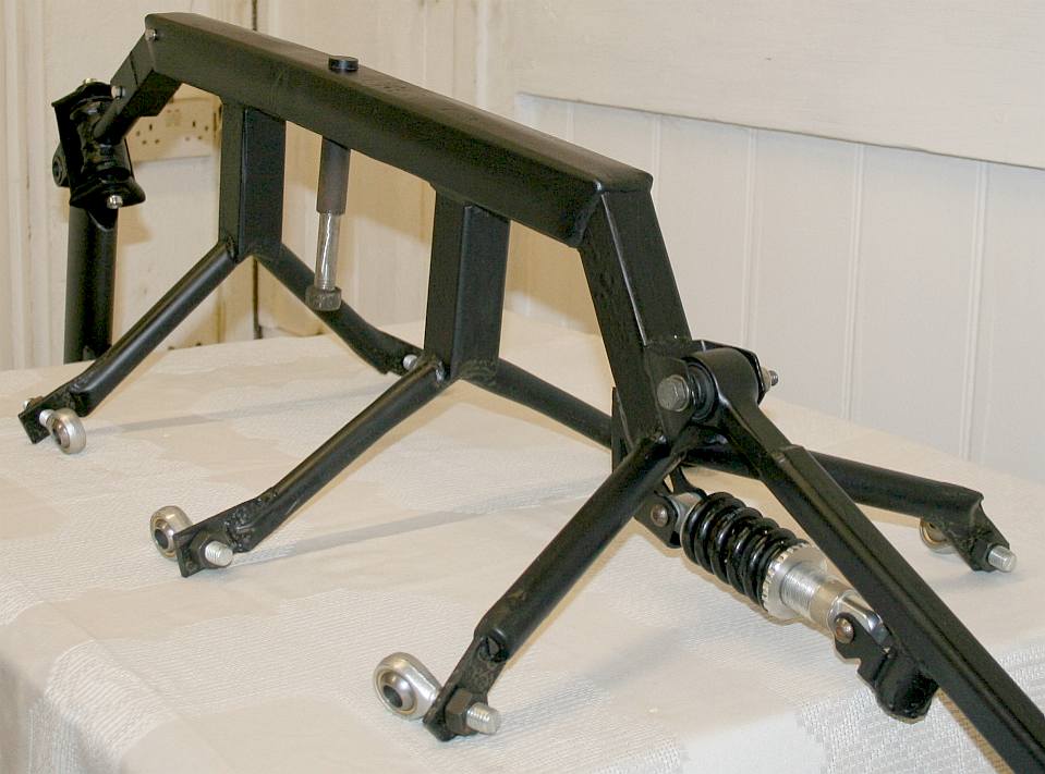
FRAME ARTICULATION - The bracket is welded in place and the tail tube and suspension coil-over-shock absorber/spring is bolted in place with a little MS3 molybdenum grease that not only lubricates the joint but also stops rusting when inside the bush for very long periods of duty. Please note that this frame is Design Copyright and that this photograph is Copyright © Jameson Hunter Ltd 31 January 2016. All rights reserved. You will need permission from Jameson Hunter to be able to reproduce it.
HEAD & JAWS - The head and jaw parts placed in roughly the right position. The neck bearings on the right need to be joined (welded) and mounts made for all three of the servos. The jaws (shown here as a cardboard pattern) need to be made in steel and composites. At the moment we're using 18mm spherical rod ends for the jaw main bearings to cope with 120 lbs of closing power and the ability to lift a person into the air. There are a lot of levers and control rod couplings to make - and some more mountings that sit on top of the head frame, for the antenna. The jaw motor drives a threaded bar that opens and closes the mandibles, further increasing the motor to driven shaft ratio, and so increasing closing torque.
LINKS & REFERENCE
Popular mechanics culture movies shark night 3ds predators blow jaws out of the water http://www.jandsfasteners.co.uk/ Chicago Zoological Park Illinois Brookfield Zoo Blog AL entertainment press register 2011 video giant_insects_exhibit Youtube Hexbug Vex robotic ant http://www.sussex.ac.uk/lifesci/insectnavigation/ http://journals.plos.org/plosone/article?id=10.1371/journal.pone.0122077 Dr Paul Graham http://www.sussex.ac.uk/lifesci/insectnavigation/ http://journals.plos.org/plosone/article?id=10.1371/journal.pone.0122077 http://www.gngebike.com/apps/webstore/products/show/3019663 http://www.electricscooterparts.com/bicyclesprockets.html https://www.aldebaran.com/ http://www.softbank.jp/en/ http://electronics.howstuffworks.com/gadgets/other-gadgets/stun-gun.htm http://lynchmotors.co.uk/ http://www.nestle.co.uk/ http://www.mufg.jp/english/ http://www.mitsubishielectric.co.uk/ http://www.mirror.co.uk/authors/olivia-solon/ http://www.maplin.co.uk/ http://www.budk.com/Stun-Guns-2974 http://www.autodesk.co.uk/products/autocad/overview https://en.wikipedia.org/wiki/Four-minute_mile http://www.bostondynamics.com/robot_bigdog.html http://www.discovery.com/ http://www.spear-and-jackson.com/products/hand-tools/hacksaw-blades http://www.mirror.co.uk/news/technology-science/technology/robot-army-future---killer-5053344 https://www.youtube.com/watch?v=O5a7xab7WRY http://zjmy-lu.en.made-in-china.com/product/YKNnjrEkZWVS/China-800W-36V-W-Bracket-Electric-Motor-Kit-W-Control-Box-Throttle-F-Scooter-My1020.html http://www.nydailynews.com/news/national/don-sex-robots-expert-article-1.2362308 http://www.theguardian.com/technology/2014/dec/01/nestle-robots-coffee-machines-japan-george-clooney-pepper-android-softbank http://www.theguardian.com/world/2015/sep/28/no-sex-with-robots-says-japanese-android-firm-softbank https://www.czs.org/Brookfield-ZOO/Home http://www.exploreum.com/ http://blog.al.com/entertainment-press-register/2011/01/video_giant_insects_exhibit_ar.html https://en.wikipedia.org/wiki/Them! http://www.imdb.com/title/tt0047573/fullcredits/ https://en.wikipedia.org/wiki/Mechatronics https://en.wikipedia.org/wiki/Animatronics http://www.instructables.com/id/Simple-Animatronics-robotic-hand/ http://www.robots.nu/robot-animals/ http://www.knbefxgroup.com/
Tel:
01524 38 33 44 http://www.jandsfasteners.co.uk/
LEFT - Movie idea, lurking beneath the Antarctic ice is a discovery that scientists will die for. This story is now the subject of a low budget trailer to be produced mostly in the UK. The promoters are looking for backers. The UK will contribute 20% toward production costs. Roughly 60% of a low budget film may be pre-sold as distribution rights, leaving 20% finance to source. The deal is that investors recover 120% on their project stake within 12 months of shooting, with an income stream thereafter from networks and merchandising. Producers and directors please take note that there is a significant audience for well made movies of this genre. Look at what happened when they remade Godzilla. RIGHT - 2015 movie inspired by the Marvel graphic novels.
A Sectasaur™ (thawed) - now on permanent display at Herstmonceux Museum, in Sussex, England.
ANTICS - ARDUINO - ARMOUR - ARTWORK - BIOLOGY - BLACK BOX - COMPUTERS - ELECTRONICS - ENERGY - FRAME - HEAD - JAWS - JIMMY WATSON - KITS - LEGS - MECHANICS - MOTORS - MOVIE - PHOTOGRAPHY - RASPBERRY Pi - R/C DRONE - SENTRY - SOFTWARE - SOUND PROOFING - SPEED - SUSPENSION - TAIL - WEAPONS - WARGAMING
DINOSAURS - DOLPHINS - HUMANOIDS - RAYS - SHARKS - WHALES
ARDUINO - ARM HOLDINGS - BEAGLEBOARD - MBED - PCBS - PICAXE - RASPBERRY PI
|
|
|
This website is Copyright © 2024 Bluebird Marine Systems Limited. The names Bluebird™, Bluefish™, Miss Ocean™, SeaNet™, SeaVax™ are trademarks. All other trademarks are hereby acknowledged. The design of the Robot Ant on this page is design copyright © December 15 2015, all rights reserved - Jameson Hunter Ltd. IMPORTANT NOTE: Under no circumstances may our products, or those of Jameson Hunter Ltd, be used by any military or law enforcement organization, for any warlike, combat, or peacekeeping crowd control purposes. Anyone purchasing one of these units will be required to sign a binding undertaking (Deed) to that effect. Any unit found to have been purchased by proxy, will be confiscated, along with civil remedy in respect of breach of contract, that all parties in the chain will be vicariously liable for - to include damages for vehicles developed from our designs without our consent - and possible fraud issue from the deception. In addition to copyright theft, the law of passing-off applies.
|